
Page 418 - Subyek Teknik Mesin - Forsthoffers Best Practice Handbook for Rotating Machinery by William E Forsthoffer
P. 418
Lube, Seal and Control Oil System Best Practices Best Practice 7 .13
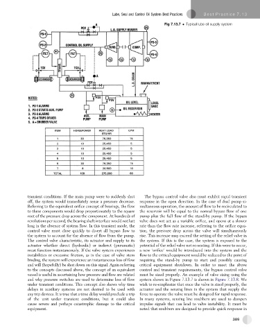
Fig 7.13.7 Typical lube oil supply system
transient conditions. If the main pump were to suddenly shut The bypass control valve also must exhibit rapid transient
off, the system would immediately sense a pressure decrease. response in the open direction. In the case of dual pump si-
Referring to the equivalent orifice concept of bearings, the flow multaneous operation, the amount of flow to be recirculated to
to these components would drop proportionately to the square the reservoir will be equal to the normal bypass flow of one
root of the pressure drop across the component. At hundreds of pump plus the full flow of the stand-by pump. If the bypass
revolutions per second, the bearing shaft interface would not last valve does not act as a variable orifice, and opens at a slower
long in the absence of system flow. In this transient mode, the rate than the flow rate increase, referring to the orifice equa-
control valve must close quickly to divert all bypass flow to tion, the pressure drop across the valve will simultaneously
the system to account for the absence of flow from the pump. rise. This increase may exceed the setting of the relief valve in
The control valve characteristic, its actuator and supply to its the system. If this is the case, the system is exposed to the
actuator whether direct (hydraulic) or indirect (pneumatic) potential of the relief valve not re-seating. If this were to occur,
must function instantaneously. If the valve system experiences anew ‘orifice’ wouldbeintroducedinto the system andthe
instabilities or excessive friction, as in the case of valve stem flow to the critical equipment would be reduced to the point of
binding, the system will experience an instantaneous loss of flow requiring the stand-by pump to start and possibly causing
and will (hopefully) be shut down on this signal. Again referring critical equipment shutdown. In order to meet the above
to the concepts discussed above, the concept of an equivalent control and transient requirements, the bypass control valve
vessel is useful in ascertaining how pressure and flow are related must be sized properly. An example of valve sizing using the
and why pressure switches are used to determine loss of flow system shown in Figure 7.13.7 is shown in Figure 7.13.8.We
under transient conditions. This concept also shows why time wish to re-emphasize that once the valve is sized properly, the
delays in auxiliary systems are not desired to be used with actuator and the sensing lines in the system that supply the
any trip devices. It is true that a time delay would preclude a trip force to operate the valve must be designed for rapid response.
of the unit under transient conditions, but it could also In many systems, sensing line snubbers are used to dampen
cause severe and perhaps catastrophic damage to the critical impulse signals that can lead to valve instability. It must be
equipment. noted that snubbers are designed to provide quick response in
389