
Page 420 - Subyek Teknik Mesin - Forsthoffers Best Practice Handbook for Rotating Machinery by William E Forsthoffer
P. 420
Lube, Seal and Control Oil System Best Practices Best Practice 7 .13
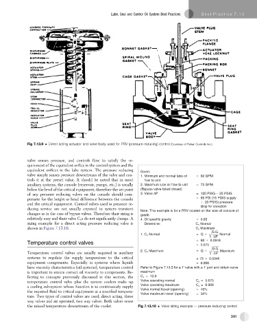
Fig 7.13.9 Direct acting actuator and valve body used for PRV (pressure reducing) control (Courtesy of Fisher Controls Inc.)
valve senses pressure, and controls flow to satisfy the re-
quirement of the equivalent orifice in the control system and the
equivalent orifices in the lube system. The pressure reducing
Given:
valve simply senses pressure downstream of the valve and con- 1. Minimum and normal lube oil = 60 GPM
trols it at the preset value. It should be noted that in most flow to unit
auxiliary systems, the console (reservoir, pumps, etc.) is usually 2. Maximum lube oil flow to unit = 73 GPM
below the level of the critical equipment; therefore the set point (Bypass valve failed closed)
of any pressure reducing valves on the console should com- 3. Valve P = 120 PSIG 25 PSIG
pensate for the height or head difference between the console = 95 PSI (15 PSIG supply
20 PSIG) pressure
and the critical equipment. Control valves used in pressure re- drop for elevation
ducing service are not usually exposed to system transient Note: This example is for a PRV located on the lube oil console at
changes as in the case of bypass valves. Therefore their sizing is grade.
relatively easy and their valve C v s do not significantly change. A 4. Oil specific gravity = 0.85
sizing example for a direct acting pressure reducing valve is D r e t e m n i : e C v Normal
shown in Figure 7.13.10. C v Maximum
S G
1. C v Normal = Q Normal
P P
= 60 0.0946
Temperature control valves = 5.675
G
2. C v Maximum = Q Maximum
Temperature control valves are usually required in auxiliary P
systems to regulate the supply temperature to the critical = 73 0.0946
equipment components. Especially in systems where liquids = 6.906
have viscosity characteristics (oil systems), temperature control Refer to Figure 7.13.5 for a 1' valve with a 1' port and obtain valve
is important to ensure correct oil viscosity to components. Re- maximum
ferring to concepts previously discussed in this section, the C v = 12.0
temperature control valve plus the system coolers make up Valve operating normal C v = 5.675
a cooling sub-system whose function is to continuously supply Valve operating maximum C v = 6.906
Valve normal travel (opening) = 40%
the required fluid to critical equipment at a specified tempera- Valve maximum travel (opening) = 50%
ture. Two types of control valves are used; direct acting, three
way valves and air operated, two way valves. Both valves sense
the mixed temperature downstream of the cooler. Fig 7.13.10 Valve sizing example e pressure reducing control
391