
Page 425 - Subyek Teknik Mesin - Forsthoffers Best Practice Handbook for Rotating Machinery by William E Forsthoffer
P. 425
Be st Practice 7 .15 Lube, Seal and Control Oil System Best Practices
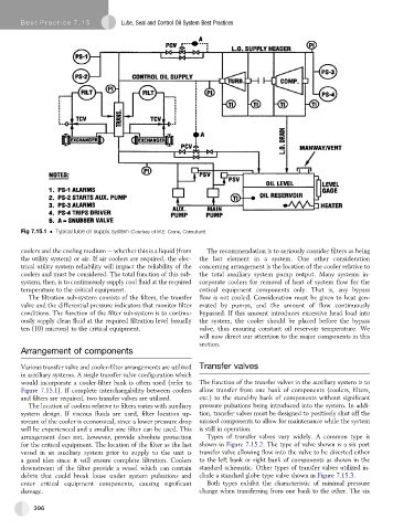
Fig 7.15.1 Typical lube oil supply system (Courtesy of M.E. Crane, Consultant)
coolers and the cooling medium e whether this is a liquid (from The recommendation is to seriously consider filters as being
the utility system) or air. If air coolers are required, the elec- the last element in a system. One other consideration
trical utility system reliability will impact the reliability of the concerning arrangement is the location of the cooler relative to
coolers and must be considered. The total function of this sub- the total auxiliary system pump output. Many systems in-
system, then, is to continuously supply cool fluid at the required corporate coolers for removal of heat of system flow for the
temperature to the critical equipment. critical equipment components only. That is, any bypass
The filtration sub-system consists of the filters, the transfer flow is not cooled. Consideration must be given to heat gen-
valve and the differential pressure indicators that monitor filter erated by pumps, and the amount of flow continuously
conditions. The function of the filter sub-system is to continu- bypassed. If this amount introduces excessive head load into
ously supply clean fluid at the required filtration level (usually the system, the cooler should be placed before the bypass
ten (10) microns) to the critical equipment. valve, thus ensuring constant oil reservoir temperature. We
will now direct our attention to the major components in this
section.
Arrangement of components
Various transfer valve and cooler-filter arrangements are utilized Transfer valves
in auxiliary systems. A single transfer valve configuration which
would incorporate a cooler-filter bank is often used (refer to The function of the transfer valves in the auxiliary system is to
Figure 7.15.1). If complete interchangability between coolers allow transfer from one bank of components (coolers, filters,
and filters are required, two transfer valves are utilized. etc.) to the stand-by bank of components without significant
The location of coolers relative to filters varies with auxiliary pressure pulsations being introduced into the system. In addi-
system design. If viscous fluids are used, filter location up- tion, transfer valves must be designed to positively shut off the
stream of the cooler is economical, since a lower pressure drop unused components to allow for maintenance while the system
will be experienced and a smaller size filter can be used. This is still in operation.
arrangement does not, however, provide absolute protection Types of transfer valves vary widely. A common type is
for the critical equipment. The location of the filter as the last shown in Figure 7.15.2. The type of valve shown is a six port
vessel in an auxiliary system prior to supply to the unit is transfer valve allowing flow into the valve to be diverted either
a good idea since it will ensure complete filtration. Coolers to the left bank or right bank of components as shown in the
downstream of the filter provide a vessel which can contain standard schematic. Other types of transfer valves utilized in-
debris that could break loose under system pulsations and clude a standard globe type valve shown in Figure 7.15.3.
enter critical equipment components, causing significant Both types exhibit the characteristic of minimal pressure
damage. change when transferring from one bank to the other. The six
396