
Page 427 - Subyek Teknik Mesin - Forsthoffers Best Practice Handbook for Rotating Machinery by William E Forsthoffer
P. 427
Be st Practice 7 .15 Lube, Seal and Control Oil System Best Practices
Fig 7.15.4 Typical shell and tube cooler
tube design, if a suitable cooling liquid is available (refer to root systems and pressure surveys for existing utility systems
Figure 7.15.4). are performed. In specifying coolers for auxiliary systems,
If water is not available on site, an air cooler (fin fan) is used, attention should be paid to minimizing gasket and ‘O’ ring
and is usually mounted on the auxiliary equipment skid (see interfaces that could cause leakage of cooling fluid into the
Figure 7.15.5). auxiliary system. Good auxiliary system design dictates that
Cooler selection is based on total auxiliary system heatload. the auxiliary system fluid always be at a greater pressure than
This is obtained by adding individual component heatloads, in- the cooling fluid. This is to ensure that leakage, if it exists,
cluding the pumps, and incorporating a service factor based on will be from the auxiliary system fluid to the cooling fluid,
the duty. Typically, a service factor of 10 to 20% excess ex- thereby eliminating the possibility of introducing cooling fluid
changer surface is used. As in any critical equipment auxiliary into the auxiliary system, and providing a means to determine
system, proper component specification is mandatory. A typical such an abnormality (by observing auxiliary system fluid
cooler data sheet is shown in Figure 7.15.6. changes).
Attention is drawn to proper specification of the cooler
fouling factor. Frequently, the condition of the utility cooling Reliability considerations
water system for shell and tube exchangers is not properly
stated, and excess fouling leads to insufficient cooling capacity - Attention should be paid to water side oil cooler pressure
available in the system. drop and the valve position of temperature control of valves,
As mentioned for pump drivers that incorporate expansion if present, during normal operation to ensure knowledge of
turbines, the same principle applies in this case. That is, the cooler performance condition.
utility cooling water system must be specified for conditions - The sudden decrease of oil reservoir level in systems where
present at the cooler flanges and not at the unit boundary. It cooler system pressure exceeds cooling fluid pressure
is recommended that cooling system calculations for grass indicates the possibility of internal cooler leakage. In
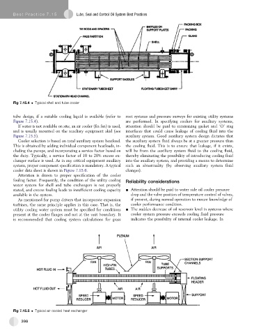
Fig 7.15.5 Typical air cooled heat exchanger
398