
Page 429 - Subyek Teknik Mesin - Forsthoffers Best Practice Handbook for Rotating Machinery by William E Forsthoffer
P. 429
Be st Practice 7 .15 Lube, Seal and Control Oil System Best Practices
system fluid bypass. Any bypassing of oil to be filtered will
result in critical equipment wear and damage. Even though
a filter is designed to eliminate bypass, care must be exercised
during maintenance to ensure that all filter cartridges and
sealing components are properly installed. In addition, during
maintenance, care must be taken to preclude the possibility of
dirt and debris falling from used filter cartridges and entering
the system. In this case, reintroduction of this filter debris into
the system will cause debris to directly enter the equipment
components. Recent developments in filter design include
modifications to ensure complete sealing and also minimize the
possibility of entrance of debris into the system during
maintenance.
Also of importance is the selection of filter cartridge material
and configuration. Attention must be paid to the auxiliary
system fluid and the selection of filter cartridge material to
ensure deterioration of cartridges does not take place during
operation. Also of note is the recommendation to minimize
Fig 7.15.7 Surface type filter (Courtesy of Hilco) cartridge interfaces as much as possible in a filter. Use of ele-
ments stacked one high instead of typical multi-stacked ele-
ments minimizes potential for internal filter bypass. Note that
most current filter applications can be modified to eliminate
multi-stacked elements. The specification of clean filter pres-
sure drop is important to ensure proper filtration and minimum
filter maintenance. It is suggested that clean filter pressure drop
is limited to a maximum of five (5) psi. Attention must be paid
to maximum filter cartridge allowable pressure drop and dif-
ferential filter alarms set at a level to preclude the possibility of
filter collapse.
Fig 7.15.8 Depth type filter (Courtesy of Filterrite)
Increasing the filter debris load will increase filter differential
pressure, thereby signaling the need for transfer to the other
filter bank to allow maintenance to change the dirty filter
elements.
There are essentially two main types of filters elements
employed in critical equipment auxiliary systems. The first type
is shown in Figure 7.15.7, and is a surface filter, and the second
type, in Figure 7.15.8, is the depth type filter. Different users
and vendors have different preferences. Both filters are efficient
and are employed in critical equipment systems.
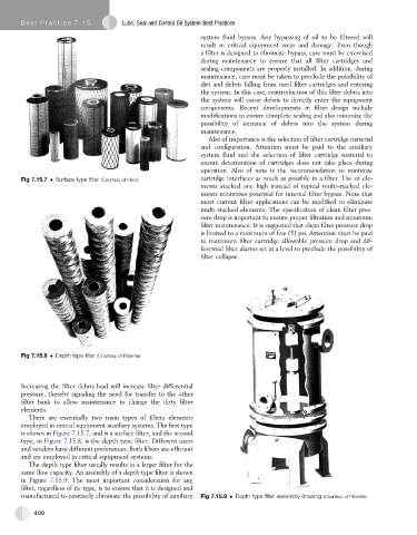
The depth type filter usually results in a larger filter for the
same flow capacity. An assembly of a depth type filter is shown
in Figure 7.15.9. The most important consideration for any
filter, regardless of its type, is to ensure that it is designed and
manufactured to positively eliminate the possibility of auxiliary Fig 7.15.9 Depth type filter assembly drawing (Courtesy of Filterrite)
400