
Page 423 - Subyek Teknik Mesin - Forsthoffers Best Practice Handbook for Rotating Machinery by William E Forsthoffer
P. 423
Be st Practice. 7.14 Lube, Seal and Control Oil System Best Practices
Given:
System required flow = 120 GPM
System pressure at accumulator (at which accumulator effect is
desired) = 140 PSIG – 154.7 PSIA (P2)
Gas precharge pressure (pressure at which accumulator oil flow
ceases, assuming system pressure does not fall below this
level) = 110 PSIG = 124.7 PSIA (P 1 )
Volume of accumulator = 9 gallons (V a ) (accounts for volume
of internal parts)
Determine:
Amount of oil required
Number of 10 gallon accumulators required
Amount of oil required:
120 Gal/Min
System flow per second =
60 Sec/Min
= 2 Gal/Sec
Oil required = 3 Sec. 2 Gal/Sec
= 6 Gallons
Volume of oil entering system for each 10 gallon accumulator.
V oil =(V a )
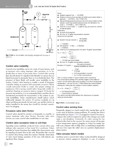
Fig 7.14.2 Accumulator precharging arrangement (Courtesy of
Elliott Co.) = (9 Gal)
= 1.75 Gal. per accumulator
Number of 10 gallon accumulators required
Oil quantity required
Control valve instability Number of 10 gallon = Quantity available per accum:
Control valve instability can be the result of many factors, such 6Gal:
accumulators =
as improper valve sizing, improper valve actuators, air in hy- 1:75 Gal:
draulic lines or water in pneumatic lines. Control valve sensing = 3.42 accumulators required
lines should always be supplied with bleeders to ensure that no = four 10 Gal. accumulators
liquid is present in pneumatic lines or air in hydraulic lines. The This is a large number of accumulators and is caused by:
presence of these fluids will usually cause instability in the The conservative setting of P2 and the neglect of the effect of
system. Control valve hunting is usually a result of improper system control valves and partial auxiliary pump flow during pump
controller setting on systems with pneumatic actuators. Please acceleration. Let's set P2 just (1 PSIG) below the normal header
setting and recalculate the number of accumulators required.
consult instruction books to ensure that proper settings are
maintained. Direct-acting control valves frequently exhibit in- V oil =
stabilities (hunting on transient system changes). If checks for = 2.6 Gal/accumulator
air prove inconclusive, it is recommended that a snubber device = 3 accumulators required
(mentioned previously) be incorporated in the system to pre- The above example demonstrates the importance of properly
vent instabilities. Some manufacturers install orifices which sizing an accumulator.
sufficiently dampen the system. If systems suddenly act up
where problems previously did not exist, any snubber device or Fig 7.14.3 Accumulator sizing
orifice installed in the sensor line should be checked immedi-
ately for plugging. Control valve sensing lines
Excessive valve stem friction Frequently, plugged or closed control valve sensing lines can be
a root cause of auxiliary system problems. If a sensing line that is
Control valves should be stroked as frequently as possible, to dead-ended (see Figure 7.13.7) is plugged or closed at its source,
ensure minimum valve stem friction. Excessive valve stem a bypass valve will not respond to system flow changes and could
friction can cause control valve instabilities or unit trips. cause a unit shutdown. Conversely, if a valve sensing line has
ableed orifice back to the reservoir (to ensure proper oil viscosity
Control valve excessive noise or unit trips in low temperature regions), plugging or closing the supply line
Squealing noises suddenly produced from control valves may will cause a bypass valve to fully close, so rendering it inoperable
indicate valve operation at low travel (C v ) conditions. Valves and may force open the relief valve in a positive displacement
installed in bypass functions that exhibit this characteristic may pump system.
be signaling excessive flow to the unit. Remember the concept
of control valves being crude flow meters. Periodic observation Valve actuator failure modes
of valve travel during operation of the unit will indicate any Auxiliary system control valve failure modes should be designed
significant flow changes. to prevent critical equipment shutdown in case of actuator
394