
Page 419 - Subyek Teknik Mesin - Forsthoffers Best Practice Handbook for Rotating Machinery by William E Forsthoffer
P. 419
Be st Practice 7 .13 Lube, Seal and Control Oil System Best Practices
of a dynamic pump. A pressure reducing valve set to sense the
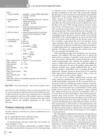
Given: pressure downstream of the valve will automatically regulate
1. Normal valve flow = pump flow – normal system requirement the discharge, or the back pressure on the dynamic pump for the
=73 GPM 60 GPM
desired flow of the system. Referring back to the equivalent
=13 GPM
2. Maximum valve = main and auxiliary pump flow – minimum orifice concept, if a bearing were to wear, the equivalent di-
flow system requirement ameter of the orifice would increase. Therefore, initially for the
same flow rate, the pressure in the system would decrease since
= 146 GPM 60 GPM
=86 GPM the flow is the same. If the bearing clearance increases (equiv-
3. Maximum valve P = pump discharge pressure @ maximum alent D), the 6P must decrease. Therefore the pressure control
supply flow and component P valve sensing decreasing system pressure will open to increase
= 250 PSIG the system pressure. This action will result in a decrease of re-
4. Minimum valve P = pump discharge pressure @ minimum sistance on the dynamic pump discharge flange and allow the
supply flow and component P (clean centrifugal pump to operate at a greater capacity to provide the
system)
= 160 PSIG desired flow to the critical equipment. It can be seen that in this
5. Oil specific gravity = 0.85 case, the pressure reducing valve and the dynamic pump com-
DETERMINE: C v Minimum bine to produce a sub-system that meets the objective of pro-
C Maximum viding continuous flow to the critical equipment. The control
v
S G valve essentially renders the variable flow, constant head device
1. C v Min. = Q NORMAL
PMax a variable head device by compensating for changes in system
= 13 0.0583 pressure. The above case represents the normal control case.
= .758 Let’s now examine the transient case.
SG If the main dynamic pump were suddenly to trip, the system
2. C v Max. = Q MAX.
PMin pressure will suddenly fall since greater flow is exiting the
= 86 0.0729 system than is entering it (‘equivalent vessel concept’). In this
= 6.268 case, the pressure reducing valve sensing downstream pressure
3
Refer to Figure 6.5 for 1'' valve with / 4'' port and obtain:
would instantaneously open allowing the dynamic pump to
Valve maximum C = 7.0 move to a higher flow point on its curve, while the auxiliary or
v
Valve operating C v = 6.268
maximum stand-by pump starts. As soon as the auxiliary pump starts, the
pressure reducing valve, sensing additional flow into a fixed
Valve operating C v = 0.758
minimum system resistance, would then close, so meeting the flow re-
Valve maximum travel = 90% quirements. Dynamic systems in general tend to be somewhat
(opening) softer than positive displacement systems. That is, they are
Valve minimum travel =9% more tolerable to transient system changes.
(opening) In the case of the auxiliary stand-by pump and the main
Note: Valve minimum and maximum openings are at the limit for pump operating simultaneously, the pressure reducing valve
satisfactory operation.
would automatically compensate for the increased flow by re-
ducing its travel or increasing the system resistance at the dis-
Fig 7.13.8 Valve sizing example e back pressure (bypass) control charge flange of both pumps. That is, increasing the discharge
pressure to the level where the combined flow of both pumps
one direction and retarded or slower response in another. It is would exactly equal the critical equipment system required
of extreme importance that these devices be installed properly. flow. Again referring to the concept of an equivalent orifice, if
Understanding the function of the particular valve in question excessive flow were forced through the orifice (the bearings) the
and examining the direction of the snubber device in a sensing pressure drop would increase. The pressure reducing valve,
line is essential to correct system operation. Many times these sensing the increased system pressure drop, would tend to close
snubber devices are installed improperly in the wrong to reduce the pressure at its sense point. In doing so it will in-
direction. crease the discharge pressure on both dynamic pumps, and since
their characteristic is reduced flow on increased pressure, the
desired flow will be obtained. Therefore it can be seen again that
Pressure reducing control the dynamic pump pressure reducing valve sub-system has the
function of flow control to the critical equipment even though it
Pressure reducing control has two primary applications in aux- is sensing pressure.
iliary systems: The other primary application for pressure reducing valves in
auxiliary systems is to reduce system pressure to other desired
- To control the flow from a dynamic pump.
- To reduce the pressure in the system. pressure levels. Refer to Figure 7.13.7, and observe the pressure
reducing valve at the discharge of the lube oil system. Its
A typical pressure reducing control valve and actuator are function is to reduce pressure from control oil pressure to lube
shown in Figure 7.13.9. oil pressure. Control oil pressure is controlled by the equivalent
For the first case, the flow characteristic is variable. The flow orifice in the control system and the set point of the bypass
is therefore determined by the pressure at the discharge flange control valve, as shown in Figure 7.13.7. The bypass control
390