
Page 417 - Subyek Teknik Mesin - Forsthoffers Best Practice Handbook for Rotating Machinery by William E Forsthoffer
P. 417
Be st Practice 7 .13 Lube, Seal and Control Oil System Best Practices
experience that travel indicators are not often supplied with the
valve. It is strongly recommended that valve travel indicators be
Body Port % Travel Valve Travel
supplied or retrofitted in the field.
size size (12.5%) (25.0%) (50%) (75%) (100%)
1/32" 1/16" 1/8" 3/16" ¼"
1'' 3/4 1.4 3.1 4.2 5.3 7.0 Bypass control
1'' 1'' 2.4 4.2 7.0 10.0 12
The first application to be discussed in this section will be that of
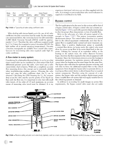
Fig 7.13.5 Typical liquid valve sizing coefficient table a bypass control valve. A bypass control valve and actuator pic-
tured in Figure 7.13.6 is used with a positive displacement pump
to alter the pump’s flow characteristic to that of variable flow.
When dealing with viscous liquids, as in the case of oil, valve
Refer to the schematic of a lube oil system typical of the
coefficient viscosity corrections must be made. For the example example in Figure 7.13.7. This system incorporates positive
case mentioned above, the correction factor for 220 centistokes displacement pumps. The control valve’s function is to control
(1,000 Sabolt Universal Seconds [SSU]) would be approxi- flow to the critical equipment continuously, such that the re-
mately 1.5 to 2. Therefore the valve coefficient required would quired flow is supplied under normal and under transient con-
be 1.5 to 2 times that required at normal viscosities (60 SSU for ditions. Since a positive displacement pump is essentially
light turbine oil at normal operating temperatures). Viscosity a constant flow device, in bypass mode the control valve must
correction nomographs are available from control valve manu- allow for excess pump flow to be recirculated back to the res-
facturers for determining valve sizes required under high vis- ervoir. Utilizing the concept of an equivalent orifice, as the
cosity conditions. bearings in the system wear, the orifice diameter becomes
larger, therefore the flow required to the critical equipment will
A flow meter in every system be greater. Since the downstream pressure across the bearings is
Considering the relationship discussed above, it can be seen that atmospheric pressure, the upstream pressure will initially de-
every control valve can be considered as a flow meter if the fluid crease when the bearing area becomes larger for the same flow.
differential pressure across the valve, valve travel and a valve The bypass valve will sense the upstream pressure reducing, and
characteristic chart is known. While not a completely accurate will close to force the additional required flow to the critical
flow measuring device, this concept can be extremely valuable equipment. Even though the bypass valve is a pressure device, it
when troubleshooting auxiliary systems. Obtaining the valve is acting as a flow control device to divert bypass flow to required
travel and using the valve coefficient chart, the C v can be system components. Therefore using the concept of a sub-
obtained. Calculating for GPM knowing the C v , the pressure system, the bypass valve and the positive displacement pump
drop across the valve and the specific gravity of the liquid can form a variable flow sub-system that will supply variable flow to
then yield the flow rate. It is important to note that with small the critical equipment on demand.
valve travels, of the order of 1/4 inch maximum, an accurate In addition to accounting for small changes in system flow
means of measuring valve travel must be obtained. It is my requirements, the bypass control valve must also act under
Fig 7.13.6 Reverse acting actuator and valve body typically used as a back pressure regulator (bypass control) (Courtesy of Fisher Controls Inc.)
388