
Page 422 - Subyek Teknik Mesin - Forsthoffers Best Practice Handbook for Rotating Machinery by William E Forsthoffer
P. 422
Lube, Seal and Control Oil System Best Practices Best Practice. 7.14
Best Practice. 7.14Practice. 7.14Practice. 7.14
Best
Best
Install dual SS accumulators in critical equipment lube oil personnel use to ensure that the accumulator is put back into service
systems to positively prevent unit low oil pressure trips slowly to prevent a decrease in oil pressure.
during transient events. Oil systems can be easily modified for installation of an accumulator
Even a properly designed lube oil system will eventually experience during a turnaround.
trips during transient events due to the following facts:
Lessons Learned
The bypass (backpressure) valve response will change (packing
friction) Lube oil systems installed without accumulators will
The bypass (backpressure) valve sensing line pulsation valve can eventually cause critical (un-spared) unit trips that will
become clogged expose the user to significant revenue losses.
The auxiliary pump start time will increase (electrical system Clients with critical lube oil systems without accumulators will often
changes) install them eventually, after experiencing unit trips that can easily
justify the modification costs.
Installation of two (2) stainless steel accumulators, each sized for 4
seconds of oil supply, will prevent unit low pressure trips and allow Benchmarks
plant personnel to check accumulator pre-charge and bladder condi-
tion periodically (every 3 months) without taking the accumulator out of This best practice has been used since the 1990s when FAI performed
service. numerous field audits for auxiliary systems. Installed accumulators
It is also recommended that an orifice bypass line with a globe value immediately increased critical unit MTBFs and increased unit reliability
be installed around (in parallel to) the accumulator supply line for significantly.
B.P. 7.14. Supporting Material
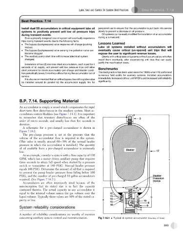
An accumulator is simply a vessel which compensates for rapid
short term flow disturbances in the auxiliary system. Most ac-
cumulators contain bladders (see Figure 7.14.1). It is important
to remember that transient disturbances are often of the
order of micro seconds, and usually less than five seconds in
duration.
A schematic for a pre-charged accumulator is shown in
Figure 7.14.2.
The pre-charge pressure is set at the pressure that the
volume of the accumulator flow is required in the system.
(This value is usually around 60e70% of the normal header
pressure in which the accumulator is installed.) The quantity
of oil available from a pre-charged accumulator is extremely
low.
As an example, consider a system with a flow capacity of 120
GPM, which has a motor driven auxiliary pump that requires
three seconds to attain full speed when started by a pressure
switch or transmitter at 140 PSIG. Normal header pressure
equals 160 PSIG. Determine the amount of oil that is required
to prevent the pump header pressure from falling below 100
PSIG, and the number of pre-charged 10 gallon accumulators
required. (See Figure 7.14.3.)
Accumulators are often improperly sized because of the
misconception that its stated size is in fact the capacity
contained therein. The actual capacity in any accumulator is
equal to the internal volume minus the gas volume over the
liquid volume. Typically these values are 50% of the stated ca-
pacity or less.
System reliability considerations
A number of reliability considerations are worthy of mention
concerning auxiliary system control and instrumentation. Fig 7.14.1 Typical oil system accumulator (Courtesy of Greer)
393