
Page 406 - Subyek Teknik Mesin - Forsthoffers Best Practice Handbook for Rotating Machinery by William E Forsthoffer
P. 406
Lube, Seal and Control Oil System Best Practices Be st Practice 7.9
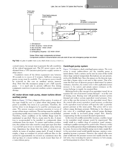
Fig 7.9.2 Lube oil system main pump shaft-driven (Courtesy of Elliott Co.)
current) source, for enough time to promote the safe coastdown Centrifugal pump system
of the critical equipment unit. The DC power source can be Figure 7.9.4 depicts a dual centrifugal pump system. The main
obtained from a UPS (uninterrupted power supply) system or
pump is steam turbine-driven and the stand-by pump is
other source. motor-driven. Such a system can be used in areas of the world
Coastdown times of the driven equipment vary between
where large ambient temperature fluctuations are not present,
30secondstoin excessof4 minutes. Sufficient emergency such as the Middle East. Since the pumps are the dynamic type,
pump energy must be available. The emergency pump would
be activated in this case on auxiliary system pressure note that a bypass valve is not used in this system. This is be-
cause the flow rate of dynamic pumps is determined by system
drop. Note that the emergency pump is not a full capacity resistance, therefore, the control valve in this application senses
pump e it is sized only to provide sufficient flow during pressure in the system and adjusts system resistance at the
equipment coastdown to prevent auxiliary system component pump discharge to supply the required flow.
damage.
Referring back to the concept of an equivalent vessel, let us
examine the case of increased system demand e as in the case
AC motor-driven main pump, steam turbine driven
of bearing wear. Bearing wear will gradually increase system
auxiliary pump demand and reduce system equivalent vessel pressure. Con-
Refer to Figure 7.9.3 for a diagram of this system. A system of sider in this case the system to be the equivalent vessel. Since
this type would be used in a plant where dual pump driver the control valve senses equivalent vessel pressure, a reduction
power is available, but steam is at a premium. Therefore, the in the equivalent vessel pressure will open the valve to provide
turbine driver is not designed to be used for continuous oper- greater pressure at the sense point. This action will in turn
ation. This system requires continuous attention in terms of reduce pump discharge pressure. Referring to the character-
steam turbine steam conditions. The turbine must be capable of istic curve of a centrifugal pump, reduced pump discharge
accelerating rapidly since a system accumulator is not included. pressure results in increased pump output flow, thereby
Therefore, steam conditions at the turbine flange must be compensating for the increased demand requirement.
maintained as specified. That is, steam must be dry. A steam In the event of a sudden system flow increase, a sudden change
trap is recommended to be installed to continuously drain in the equivalent vessel pressure would be experienced. This
condensate from the steam. To ensure rapid turbine accelera- would result in a sudden drop of equivalent vessel pressure,
tion, the turbine inlet valve must be a snap-open type (less than resulting in a sudden opening of the control valve. However, in this
1 second full open time) to minimize auxiliary pump start-up case, the sudden pressure drop would initiate starting of the stand-
time. Experience has shown that this type of system is not by pump. As soon as the stand-by pump was to start, supply flow
reliable in terms of auxiliary pump starts. If used, it should to the equivalent vessel would quickly increase, causing a corre-
employ a large accumulator to provide sufficient flow to the sponding increase in pressure. However, the control valve sense
system for approximately ten seconds as a minimum since the point would note the pressure increase and rapidly shut the con-
start-up time of a steam turbine is much slower than that of trol valve, thus increasing the system resistance to both pumps,
a motor-driven pump. and forcing pumps to a lower flow rate.
377