
Page 398 - Subyek Teknik Mesin - Forsthoffers Best Practice Handbook for Rotating Machinery by William E Forsthoffer
P. 398
Lube, Seal and Control Oil System Best Practices Be st Practice 7.7
The other kinematic viscosity term frequently used is SSU or
Saybolt Universal Seconds. ‘SSU’ are related to centistokes by:
A. Pumped liquid data
Type SSU ¼ centistokes 4:635
Pressure and temperature – normal, maximum, minimum
Vapor pressure – normal, maximum, minimum Kinematic viscosity is related to dynamic viscosity by:
Viscosity – normal, maximum, minimum
Specific gravity Kinematic viscosity ðcentistokesÞ
B. Pump suction and discharge pressure dynamic viscosity ðcentipoiseÞ
Suction pressure – normal, maximum, minimum (high ¼ specific gravity
viscosity condition)
Discharge pressure Applying the definition of viscosity to the definition of positive
Normal – clean system condition displacement and dynamic pumps, it can be seen that viscosity
Maximum – dirty system condition
C. Pump flow data has little effect on positive displacement pump performance,
Pump rated flow ¼critical equipment required flow plus 10– since pressure is increased by operating on a fluid in a fixed space.
20% allowance for pump and critical equipment component However, dynamic pump performance is significantly affected by
wear. viscosity, since this type of pump increases the pressure by using
Pump normal flow ¼critical equipment required flow rotary blades to increase fluid velocity. The shearing force re-
D. Pump net positive suction head available (NPSH A ) quired to move a viscous fluid will reduce the fluid velocity
Confirm pump location relative to minimum operating level or produced by the blades and will reduce head produced, flow and
reservoir (Note: If pump is above liquid level state the distance efficiency and result in a significant pump horsepower increase.
on the data sheet)
Confirm NPSH A noted on data sheet is for the rated flow case Pump horsepower is determined by the relationship:
and maximum suction pressure drop case (maximum fluid Flow Head Specific Gravity
viscosity, i.e., minimum liquid temperature) Power ¼
Constant Pump Efficiency
where:
Fig 7.7.6 Operating data checklist e pump data sheet
Metric units
Most pipe friction and pump correction charts use kinematic Power ¼ KW
3
viscosity. Flow ¼ M /HR
Kinematic viscosities are expressed in: Head ¼ Meters
1 centimeter 2 S.G ¼ dimensionless
centistokes ¼ stoke ¼ Constant ¼ 3600
100 second
Pump Eff’y ¼ decimal
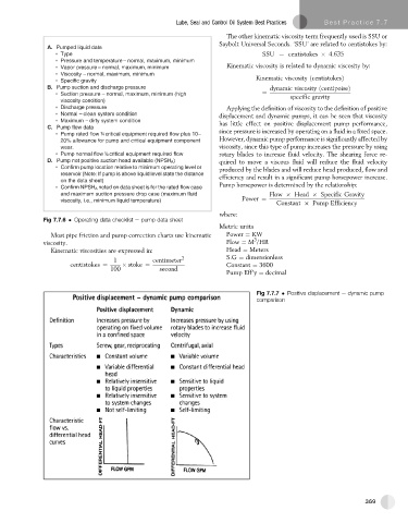
Fig 7.7.7 Positive displacement e dynamic pump
comparison
369