
Page 227 - T. Anderson-Fracture Mechanics - Fundamentals and Applns.-CRC (2005)
P. 227
1656_C004.fm Page 207 Thursday, April 21, 2005 5:38 PM
Dynamic and Time-Dependent Fracture 207
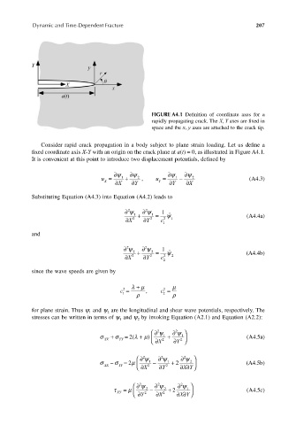
FIGURE A4.1 Definition of coordinate axes for a
rapidly propagating crack. The X, Y axes are fixed in
space and the x, y axes are attached to the crack tip.
Consider rapid crack propagation in a body subject to plane strain loading. Let us define a
fixed coordinate axis X-Y with an origin on the crack plane at a(t) = 0, as illustrated in Figure A4.1.
It is convenient at this point to introduce two displacement potentials, defined by
∂ψ ∂ψ ∂ψ ∂ψ
u = ∂ X 1 + ∂ Y 2 , u = ∂ Y 1 − ∂ X 2 (A4.3)
X
Y
Substituting Equation (A4.3) into Equation (A4.2) leads to
∂ ψ 2 1 + ∂ ψ 2 1 = 1
∂ X 2 ∂ Y 2 c 2 ψ ˙˙ 1 (A4.4a)
1
and
∂ ψ 2 2 + ∂ ψ 2 2 = 1
∂X 2 ∂Y 2 c 2 ψ ˙˙ 2 (A4.4b)
2
since the wave speeds are given by
λ + µ µ
c = , c =
2
2
1 ρ 2 ρ
for plane strain. Thus ψ and ψ are the longitudinal and shear wave potentials, respectively. The
1
2
stresses can be written in terms of ψ and ψ by invoking Equation (A2.1) and Equation (A2.2):
1
2
∂ 2 ψ ∂ 2 ψ
σ XX + σ YY λ = + µ 2( ) ∂ X 2 1 + ∂ Y 2 1 (A4.5a)
∂ 2 ψ ∂ 2 ψ ∂ 2 ψ
2
σ XX − σ YY 2 µ = ∂ X 2 1 − ∂ Y 2 1 + 2 X Y ∂∂ (A4.5b)
∂ 2 ψ ∂ 2 ψ ∂ 2 ψ
1
τ XY = µ ∂ Y 2 2 − ∂ X 2 2 + 2 X Y ∂∂ (A4.5c)