
Page 232 - T. Anderson-Fracture Mechanics - Fundamentals and Applns.-CRC (2005)
P. 232
1656_C004.fm Page 212 Thursday, April 21, 2005 5:38 PM
212 Fracture Mechanics: Fundamentals and Applications
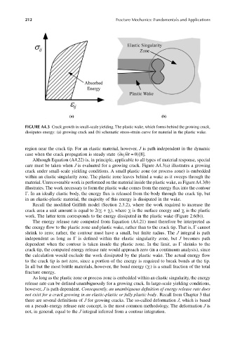
FIGURE A4.3 Crack growth in small-scale yielding. The plastic wake, which forms behind the growing crack,
dissipates energy: (a) growing crack and (b) schematic stress-strain curve for material in the plastic wake.
region near the crack tip. For an elastic material, however, J is path independent in the dynamic
ut
/
case when the crack propagation is steady state (∂∂ = 0 ) [8].
i
Although Equation (A4.22) is, in principle, applicable to all types of material response, special
care must be taken when J is evaluated for a growing crack. Figure A4.3(a) illustrates a growing
crack under small-scale yielding conditions. A small plastic zone (or process zone) is embedded
within an elastic singularity zone. The plastic zone leaves behind a wake as it sweeps through the
material. Unrecoverable work is performed on the material inside the plastic wake, as Figure A4.3(b)
illustrates. The work necessary to form the plastic wake comes from the energy flux into the contour
Γ. In an ideally elastic body, the energy flux is released from the body through the crack tip, but
in an elastic-plastic material, the majority of this energy is dissipated in the wake.
Recall the modified Griffith model (Section 2.3.2), where the work required to increase the
crack area a unit amount is equal to 2(γ + γ ), where γ is the surface energy and γ is the plastic
s
s
p
p
work. The latter term corresponds to the energy dissipated in the plastic wake (Figure 2.6(b)).
The energy release rate computed from Equation (A4.21) must therefore be interpreted as
the energy flow to the plastic zone and plastic wake, rather than to the crack tip. That is, Γ cannot
shrink to zero; rather, the contour must have a small, but finite radius. The J integral is path
independent as long as Γ is defined within the elastic singularity zone, but J becomes path
dependent when the contour is taken inside the plastic zone. In the limit, as Γ shrinks to the
crack tip, the computed energy release rate would approach zero (in a continuum analysis), since
the calculation would exclude the work dissipated by the plastic wake. The actual energy flow
to the crack tip is not zero, since a portion of the energy is required to break bonds at the tip.
In all but the most brittle materials, however, the bond energy (γ ) is a small fraction of the total
s
fracture energy.
As long as the plastic zone or process zone is embedded within an elastic singularity, the energy
release rate can be defined unambiguously for a growing crack. In large-scale yielding conditions,
however, J is path dependent. Consequently, an unambiguous definition of energy release rate does
not exist for a crack growing in an elastic-plastic or fully plastic body . Recall from Chapter 3 that
there are several definitions of J for growing cracks. The so-called deformation J, which is based
on a pseudo-energy release rate concept, is the most common methodology. The deformation J is
not, in general, equal to the J integral inferred from a contour integration.