Page 222 - T. Anderson-Fracture Mechanics - Fundamentals and Applns.-CRC (2005)
P. 222

1656_C004.fm  Page 202  Thursday, April 21, 2005  5:38 PM


                       202                                   Fracture Mechanics: Fundamentals and Applications


                       By inserting the above results into Equation (4.73), we see that J  = C*. Thus C* is a special case
                                                                           v
                       of J . The latter parameter is capable of taking account of a wide range of time-dependent material
                          v
                       behavior, and includes viscous creep as a special case.
                          Near the tip of the crack, the stresses and pseudo-strains are characterized by J  through an
                                                                                            v
                       HRR-type relationship in the form of Equation (4.33). The viscoelastic J can also be determined
                       through a pseudo-energy release rate:


                                                    J =−  1     ∂ a ∂  ∫ ∆ e Pd∆ e           (4.75)
                                                     v
                                                          B
                                                           
                                                                      
                                                                0
                                                                       ∆ e
                             e
                       where ∆ is the pseudo-displacement in the loading direction, which is related to the actual
                       displacement by
                                                          ∆     ∆ = {Dd  e }                     (4.76)

                       Finally, for Mode I loading of a linear viscoelastic material in plane strain, J  is related to the
                                                                                       v
                       stress-intensity factor as follows:

                                                              2
                                                            K 1(  −ν 2 )
                                                        J =   I  E R                             (4.77)
                                                         v
                       The stress-intensity factor is related to specimen geometry, applied loads, and crack dimensions
                       through the standard equations outlined in Chapter 2.

                       4.3.2.4 Crack Initiation and Growth

                       When characterizing crack initiation and growth, it is useful to relate J  to physical parameters
                                                                                  v
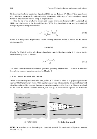
                       such as CTOD and fracture work, which can be used as local failure criteria. Schapery [59] derived
                       simplified relationships between these parameters by assuming a strip-yield-type failure zone ahead
                       of the crack tip, where a closure stress σ  acts over ρ, as illustrated in Figure 4.20. While the
                                                         m


                       FIGURE 4.20 Failure zone at the crack tip in a viscoelastic material. This zone is modeled by surface tractions
                       within 0 < x < ρ.
   217   218   219   220   221   222   223   224   225   226   227