
Page 176 - Fundamentals of Enhanced Oil and Gas Recovery
P. 176
164 Forough Ameli et al.
5.2.8.3 Feed Water
This is a significant parameter for steam production. A huge amount of input water is
needed. If there is any impurity in the system, the operation would be affected.
Dissolved minerals which lead to corrosion and make deposits on turbine blade are
precipitated and filtered using soda ash or lime. Moreover, insoluble materials such as
oil and silt that lead to scale formation are filtered. Oxygen and carbon dioxide are
deaerated, as they cause corrosion in the boiler. The cooling water which is recircu-
lated is also treated. The most challenging operation for generating steam is starting
up the heater. There may generate a flammable air and gas mixture. All operating sys-
tems must be equipped with emergency procedure for purging and also a start-up
process. As the water flow rate is low and there exists a dry boiler, the tubes would
not run correctly. On the other hand, entering the excess water into the distribution
system would damage the turbine. Boilers should equip with blowdown system for
removing the remaining water to avoid scale formation on tubes and blades of the tur-
bine. The unit is equipped with a knockout pot to eliminate the liquid from fuel gas.
There should always be an alternative source of fuel to be applied for emergency
conditions.
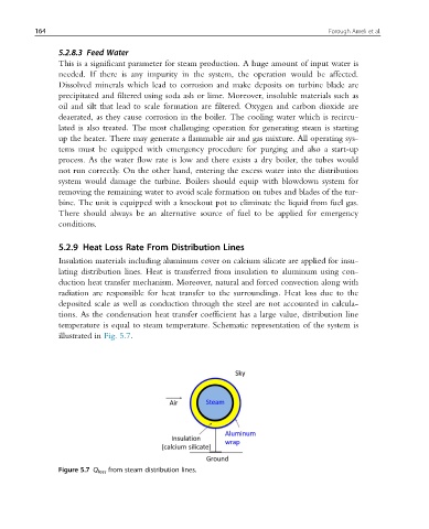
5.2.9 Heat Loss Rate From Distribution Lines
Insulation materials including aluminum cover on calcium silicate are applied for insu-
lating distribution lines. Heat is transferred from insulation to aluminum using con-
duction heat transfer mechanism. Moreover, natural and forced convection along with
radiation are responsible for heat transfer to the surroundings. Heat loss due to the
deposited scale as well as conduction through the steel are not accounted in calcula-
tions. As the condensation heat transfer coefficient has a large value, distribution line
temperature is equal to steam temperature. Schematic representation of the system is
illustrated in Fig. 5.7.
Figure 5.7 Q loss from steam distribution lines.