
Page 179 - Fundamentals of Enhanced Oil and Gas Recovery
P. 179
167
Thermal Recovery Processes
where ε is the emissivity of surface, σ is the Stefan Boltzmann constant
29 2 4
(1.713e Btu/h ft R ), T sky is the absolute sky T R( F 1 460), T g is the ground
temperature beneath pipe R (sky T D 414 515 R - in calc 5 460 R), T 3 T 2 .
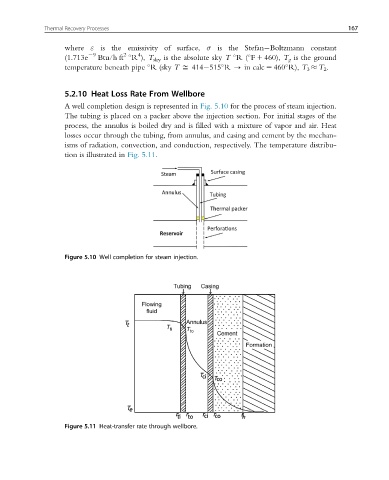
5.2.10 Heat Loss Rate From Wellbore
A well completion design is represented in Fig. 5.10 for the process of steam injection.
The tubing is placed on a packer above the injection section. For initial stages of the
process, the annulus is boiled dry and is filled with a mixture of vapor and air. Heat
losses occur through the tubing, from annulus, and casing and cement by the mechan-
isms of radiation, convection, and conduction, respectively. The temperature distribu-
tion is illustrated in Fig. 5.11.
Figure 5.10 Well completion for steam injection.
Figure 5.11 Heat-transfer rate through wellbore.