
Page 230 - Fundamentals of Enhanced Oil and Gas Recovery
P. 230
218 Mohammad Ali Ahmadi
Table 7.1 Reservoir Characterization of Field Alpha
Reservoir Data
Drainage radius (re) 1320 ft
Wellbore radius (rw) 0.25 ft
Porosity (ϕ) 20%
Absolute permeability 3 mD
Formation thickness 50 ft
Dip angle (Θ) 0
Connate water saturation (S wc ) 20%
Initial water saturation (S wi ) 35%
Residual oil saturation (S or ) 20%
Oil FVF (B o ) 1.25 bbl/STB
Water FVF (B w ) 1.02 bbl/STB
Oil viscosity 2.0 cp
Water viscosity 1.0 cp
Total injection rate 250BWPD
FVF formation volume factor.
1
0.9
0.8
Relative permeability 0.6
0.7
0.5
0.4
0.3
0.2
0.1
0
0 0.1 0.2 0.3 0.4 0.5 0.6 0.7 0.8 0.9 1
Water saturation (S )
w
K ro K rw
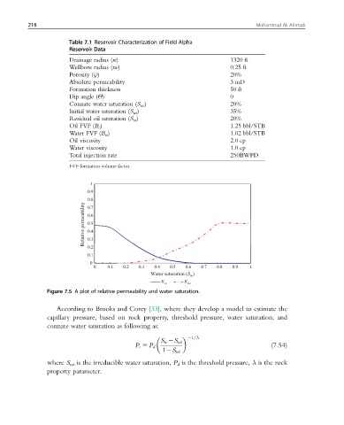
Figure 7.5 A plot of relative permeability and water saturation.
According to Brooks and Corey [33], where they develop a model to estimate the
capillary pressure, based on rock property, threshold pressure, water saturation, and
connate water saturation as following as:
21=λ
S w 2S wi
P c 5 P d (7.54)
12S wi
where S wi is the irreducible water saturation, P d is the threshold pressure, λ is the rock
property parameter.