
Page 146 - Fundamentals of Light Microscopy and Electronic Imaging
P. 146
PROPAGATION OF O AND E WAVEFRONTS IN A BIREFRINGENT CRYSTAL 129
v
v
v Propagation
of O ray
(a)
v 1
v 2
v 3 Propagation
of E ray
Fast
Slow
(b)
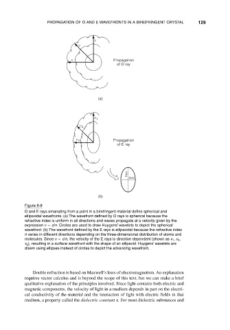
Figure 8-8
O and E rays emanating from a point in a birefringent material define spherical and
ellipsoidal wavefronts. (a) The wavefront defined by O rays is spherical because the
refractive index is uniform in all directions and waves propagate at a velocity given by the
expression v c/n. Circles are used to draw Huygens’ wavelets to depict the spherical
wavefront. (b) The wavefront defined by the E rays is ellipsoidal because the refractive index
n varies in different directions depending on the three-dimensional distribution of atoms and
molecules. Since v c/n, the velocity of the E rays is direction dependent (shown as v , v ,
2
1
v ), resulting in a surface wavefront with the shape of an ellipsoid. Huygens’ wavelets are
3
drawn using ellipses instead of circles to depict the advancing wavefront.
Double refraction is based on Maxwell’s laws of electromagnetism. An explanation
requires vector calculus and is beyond the scope of this text, but we can make a brief
qualitative explanation of the principles involved. Since light contains both electric and
magnetic components, the velocity of light in a medium depends in part on the electri-
cal conductivity of the material and the interaction of light with electric fields in that
medium, a property called the dielectric constant . For most dielectric substances and