
Page 148 - Fundamentals of Light Microscopy and Electronic Imaging
P. 148
GENERATION OF ELLIPTICALLY POLARIZED LIGHT BY BIREFRINGENT SPECIMENS 131
Fast
– C – C – C – C – C –
– C – C – C – C – C – Slow
– C – C – C – C – C –
Orientation of Wavefront
polarizable bonds ellipsoid
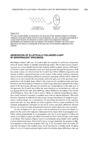
Figure 8-10
The axis of polarizability corresponds to the slow axis of the wavefront ellipse. In biological
materials composed of linear arrays of macromolecules, the axis of strongest polarizability is
usually determined by the direction of carbon-carbon bond alignments. Because
polarizability and refractive index are highest in the direction parallel to the axis of bond
alignment, this direction corresponds to the slow axis of the wavefront ellipsoid for this
material.
GENERATION OF ELLIPTICALLY POLARIZED LIGHT
BY BIREFRINGENT SPECIMENS
Birefringent objects split rays of incident light into separate O- and E-ray components
whose E vectors vibrate in mutually perpendicular planes. The O and E waves compris-
ing each ray or wave bundle also become mutually shifted in phase owing to differences
in refractive index experienced by each wave during transit through the specimen. With
the calcite crystal, we observed that the O and E rays follow different trajectories and
emerge at widely separated locations on the surface of the crystal, making it relatively
easy to examine each linearly polarized component separately with the aid of a Polaroid
sheet. Let us now consider the circumstance where the optic axis of the specimen is per-
pendicular to the incident beam, which is the usual case for retardation plates and most
biological specimens that are mounted on a microscope slide and examined in the object
plane of the microscope. Because the incident ray is perpendicular to the optic axis of
the specimen, the O and E rays follow the same trajectory as the incident ray, with one
ray lagging behind the other and exhibiting a phase difference according to the amount
of birefringence. Since the O and E waves vibrate in mutually perpendicular planes,
they cannot interfere to produce a resultant wave with an altered amplitude. This point
becomes important in polarization microscopy, because interference is required to gen-
erate a contrast image. As a convenience for describing the behavior of the superim-
posed wave pair, we may add the two waves together to form a single resultant ray. The
mutually perpendicular orientation of the two E vectors and phase difference between
the two rays result in a three-dimensional waveform called elliptically polarized light.
As seen in Figure 8-11, the E vector of the recombined wave does not vibrate in a
plane over the course of its trajectory, but progressively rotates about its propagation axis.
When viewed perpendicular to its propagation axis, the E vector appears to follow the
course of an elliptical spiral, and when viewed end-on, the E vector sweeps out the shape
of an ellipse. The resultant elliptical wave is reconstructed using simple vector addition
in three-dimensional space. For O and E waves of equal amplitude, the amount of ellip-
ticity depends on the amount of phase shift (Fig. 8-12). For phase shifts of exactly /4
and 3/4 , the shape of the resultant wave can be described as a circular spiral; for phase
shifts of or /2, linearly polarized light results; for all other phase differences (the vast