
Page 153 - Fundamentals of Light Microscopy and Electronic Imaging
P. 153
136 POLARIZATION MICROSCOPY
10 µm
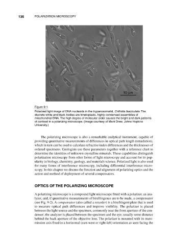
Figure 9-1
Polarized light image of DNA nucleoids in the trypanosomatid, Crithidia fasciculata. The
discrete white and black bodies are kinetoplasts, highly condensed assemblies of
mitochondrial DNA. The high degree of molecular order causes the bright and dark patterns
of contrast in a polarizing microscope. (Image courtesy of Mark Drew, Johns Hopkins
University.)
The polarizing microscope is also a remarkable analytical instrument, capable of
providing quantitative measurements of differences in optical path length (retardation),
which in turn can be used to calculate refractive index differences and the thicknesses of
ordered specimens. Geologists use these parameters together with a reference chart to
determine the identities of unknown crystalline minerals. These capabilities distinguish
polarization microscopy from other forms of light microscopy and account for its pop-
ularity in biology, chemistry, geology, and materials science. Polarized light is also used
for many forms of interference microscopy, including differential interference micro-
scopy. In this chapter we discuss the function and alignment of polarizing optics and the
action and method of deployment of several compensators.
OPTICS OF THE POLARIZING MICROSCOPE
A polarizing microscope is a compound light microscope fitted with a polarizer, an ana-
lyzer, and, if quantitative measurements of birefringence are to be made, a compensator
(see Fig. 9-2). A compensator (also called a retarder) is a birefringent plate that is used
to measure optical path differences and improve visibility. The polarizer is placed
between the light source and the specimen, commonly near the front aperture of the con-
denser; the analyzer is placed between the specimen and the eye, usually some distance
behind the back aperture of the objective lens. The polarizer is mounted with its trans-
mission axis fixed in a horizontal (east-west or right-left) orientation as seen facing the