
Page 155 - Fundamentals of Light Microscopy and Electronic Imaging
P. 155
138 POLARIZATION MICROSCOPY
this reason, manufacturers select out low strain objectives for use in polarization
microscopy.
ADJUSTING THE POLARIZING MICROSCOPE
• Focus a specimen and adjust for Koehler illumination with both polarizing filters
and compensator removed from the optical path.
• Insert the fixed polarizer (depending on the microscope, either the polarizer or ana-
lyzer might be fixed—i.e., glued into position in the holder so that it cannot rotate).
If the polarizer is fixed, its transmission axis should be oriented horizontally east-
west as seen looking in the microscope. If the polarizer is rotatable, check that the
filter is positioned correctly by looking for the mark indicating the orientation of
the transmission axis or checking the degrees of rotation on the holder.
• Insert the rotatable analyzer (or polarizer), and rotate it until the two polars are
crossed and maximum extinction is obtained. Do this by examining a blank region
on a specimen slide and making fine adjustments to the analyzer until the image is
maximally dark. The transmission axis of the analyzer should now be oriented ver-
tically or north-south. The critical adjustment for extinction can only be made while
looking in the microscope. Extinction indicates that the polars are crossed, but does
not guarantee that their azimuths are perfectly oriented east-west and north-south.
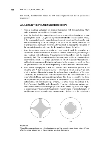
• Insert a telescope eyepiece or Bertrand lens and focus on the back aperture of the
objective lens. A dark polarization cross is observed at extinction (Fig. 9-3), with
brighter regions of intensity between the horizontal and vertical arms of the cross.
Commonly, the horizontal and vertical components of the cross are broader in the
center of the field and narrower at the periphery. This shape is caused by the depo-
larizing effects of spherical lens surfaces in the condenser and the objective lenses,
and is normal for most microscope systems. The cross should be centered in the
field of view and should be perfectly upright. If not, the polarizer and analyzer may
need to be rotated a bit to achieve proper orientation. Perfect alignment with respect
to an azimuth at 0° is essential if quantitative measurements of azimuthal angles or
birefringence are to be made with a compensator. Reference to the polarization
(a) (b)
Figure 9-3
View of the polarization cross in the back aperture of the objective lens. Views before (a) and
after (b) proper adjustment of the condenser aperture diaphragm.