
Page 157 - Fundamentals of Light Microscopy and Electronic Imaging
P. 157
140 POLARIZATION MICROSCOPY
optic axis contained in the plane of the plate. Since incident rays of linearly polarized
light are perpendicular to the optic axis of the plate, the O- and E-ray components fol-
low the same trajectory through the plate, but become retarded in phase relative to one
another; waves emerge as linearly, circularly, or elliptically polarized beams, depending
on the amount of relative phase retardation. Refer to Figure 8-12 to review how changes
in the amount of phase retardation affect the waveform and plane of vibration of resul-
tant waves emergent from the plate. The orientation of the optic axis of the plate relative
to the plane of vibration of the incident polarized light beam is important. The most
common retarders introduce phase retardations of 1 , /2, and /4 (2 , , or /2 radi-
ans) for light of a specific wavelength and are called, respectively, full-wave, half-wave,
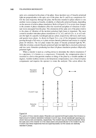
and quarter-wave plates. As shown in Figure 9-4, a ray of the designated wavelength
passing through a full-wave or plate remains linearly polarized and retains its original
plane of vibration. The /2 plate rotates the plane of linearly polarized light by 90°,
while the /4 plate converts linearly polarized light into light that is circularly polarized,
and vice versa. Retarders producing less than /4 phase retardation produce elliptically
polarized light.
When a retarder is used as a nulling device to determine the relative retardation
in a specimen, it is known as a compensator. Commonly, the compensation plate is
mounted in a device that permits rotation or tilting of the plate by a variable number of
degrees. Another method, known as de Sénarmont compensation, uses a fixed /4-plate
compensator and requires the operator to rotate the analyzer. This action allows the
Resultant
waveform
O and E rays
Retarder /4 /2
plate
Figure 9-4
The action of three retarder plates. Retarders are special birefringent plates that introduce a
fixed amount of relative retardation between O and E rays, whose wavelength spacings are
shown here as dots and dashes, respectively. The incident rays are linearly polarized. Since
the optic axis of the retarder is in the object plane and perpendicular to the incident ray, the
O and E rays follow trajectories that are superimposable, but the waves are relatively
retarded in phase.