
Page 52 - Fundamentals of Light Microscopy and Electronic Imaging
P. 52
ILLUMINATOR ALIGNMENT AND BULB REPLACEMENT 35
positioned on the optic axis of the microscope. Light from an arc lamp can be safely
examined after attenuation with a fluorescence filter set plus additional neutral density
filters. It is easier on the eye to examine the green excitation light provided by a rho-
damine filter set. A similar procedure can be applied for arc lamps used in transillumi-
nation mode.
Demonstration: Aligning a 100 W Mercury Arc Lamp
in an Epi-illuminator
• Always turn off the power supply and allow the lamp to cool completely
before changing a failed bulb. Since arc lamps are under moderately high
pressure when they are hot, an applied mechanical force can cause them to
explode. After replacing a bulb, secure the lamp socket to the lamp housing
and fasten the housing to the microscope before reigniting the lamp.
• Place neutral density filters in the light path sufficient to block 97% of the
light and place a rhodamine fluorescence filter cube into position so that the
546 nm green line of the arc is reflected onto the specimen plane. Insert addi-
tional UV- and IR-blocking filters into the path to protect the eyes.
• Tape a white card or paper on the microscope stage, focus an objective lens
until you see an intense, focused dot on the card, and mark the location with a
pen. The dot defines the position of the optic axis of the microscope (Fig. 3-3).
• Without disturbing the card, rotate the objective turret to an empty position
and observe an intense, extended spot of light on the card. Focus the collec-
tor lens of the lamp until the bright primary image of the arc is sharply
defined. If the arc’s image does not coincide with the dot, you will need to
adjust the bulb using the adjustment screws on the illuminator housing.
• There should also be a dimmer reflection image of the arc, which is focused
and aligned using the reflector’s adjustment screws on the lamp housing.
Position the reflection image so that it is on top of or next to the primary
image of the arc.
• Slowly defocus the lamp collector lens and ascertain that the beam expands
uniformly around the black dot on the card. This is an important test of
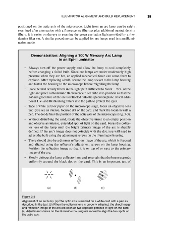
(a) (b) (c)
Figure 3-3
Alignment of an arc lamp. (a) The optic axis is marked on a white card with a pen as
described in the text. (b) When the collector lens is properly adjusted, the direct image
and reflection image of the arc are seen as two separate patches of light on the card.
(c) Adjustment screws on the illuminator housing are moved to align the two spots on
the optic axis.