
Page 57 - Fundamentals of Light Microscopy and Electronic Imaging
P. 57
40 ILLUMINATORS, FILTERS, AND THE ISOLATION OF SPECIFIC WAVELENGTHS
Incident
waves
Reflected waves Metallic layers
modified Transmitted
by interference wavelength
/2 dielectric layer
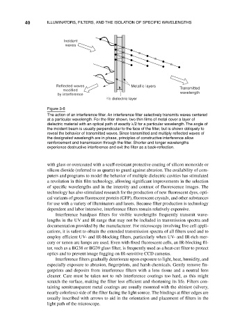
Figure 3-6
The action of an interference filter. An interference filter selectively transmits waves centered
at a particular wavelength. For the filter shown, two thin films of metal cover a layer of
dielectric material with an optical path of exactly /2 for a particular wavelength. The angle of
the incident beam is usually perpendicular to the face of the filter, but is shown obliquely to
reveal the behavior of transmitted waves. Since transmitted and multiply reflected waves of
the designated wavelength are in phase, principles of constructive interference allow
reinforcement and transmission through the filter. Shorter and longer wavelengths
experience destructive interference and exit the filter as a back-reflection.
with glass or overcoated with a scuff-resistant protective coating of silicon monoxide or
silicon dioxide (referred to as quartz) to guard against abrasion. The availability of com-
puters and programs to model the behavior of multiple dielectric cavities has stimulated
a revolution in thin film technology, allowing significant improvements in the selection
of specific wavelengths and in the intensity and contrast of fluorescence images. The
technology has also stimulated research for the production of new fluorescent dyes, opti-
cal variants of green fluorescent protein (GFP), fluorescent crystals, and other substances
for use with a variety of illuminators and lasers. Because filter production is technology
dependent and labor intensive, interference filters remain relatively expensive.
Interference bandpass filters for visible wavelengths frequently transmit wave-
lengths in the UV and IR range that may not be included in transmission spectra and
documentation provided by the manufacturer. For microscopy involving live cell appli-
cations, it is safest to obtain the extended transmission spectra of all filters used and to
employ efficient UV- and IR-blocking filters, particularly when UV- and IR-rich mer-
cury or xenon arc lamps are used. Even with fixed fluorescent cells, an IR-blocking fil-
ter, such as a BG38 or BG39 glass filter, is frequently used as a heat-cut filter to protect
optics and to prevent image fogging on IR-sensitive CCD cameras.
Interference filters gradually deteriorate upon exposure to light, heat, humidity, and
especially exposure to abrasion, fingerprints, and harsh chemicals. Gently remove fin-
gerprints and deposits from interference filters with a lens tissue and a neutral lens
cleaner. Care must be taken not to rub interference coatings too hard, as this might
scratch the surface, making the filter less efficient and shortening its life. Filters con-
taining semitransparent metal coatings are usually mounted with the shiniest (silvery,
nearly colorless) side of the filter facing the light source. The bindings at filter edges are
usually inscribed with arrows to aid in the orientation and placement of filters in the
light path of the microscope.