
Page 248 - Fundamentals of Magnetic Thermonuclear Reactor Design
P. 248
First Wall Components Chapter | 7 229
configuration shapes up. This takes around 60 s. All this time, the plasma is in
direct contact with the limiters. As there are only two limiters in the reactor, it is
important to ensure a uniform heat flux distribution on the limiters’ surfaces. To
this end, the surfaces have to be carefully formed. The same considerations are
valid when imposing very tight requirements on the limiter fabrication precision
−2
and positioning accuracy. The peak heat load on the limiters is up to ∼8 MW/m
during the start-up and the final stages of the operation cycle. At other stages, the
thermal conditions for the limiters and the FW are more or less the same.
The discharge chamber area as measured around the plasma column is close
2
to 544 m (∼80% of total projection area); the divertor chamber baffle and the
2
port limiter occupy around 77 and 9 m , or ∼11% and 1.3%, respectively. The
rest of the near-plasma space is occupied by ports allowing additional heating
and diagnostics of the plasma, as well as a remote maintenance of in-chamber
components using robotic technologies.
One a priori effective design approach to ensuring ITER availability, radiation
safety and ecological sustainability is to rely, wherever possible, on well-tested
and robust concepts, techniques, processes and materials. For unique experimen-
tal projects, to which ITER belongs, following the engineering conservatism
principle is an imperative. It is for this reason that the ITER design adopted the
traditional tokamak first wall configuration: the static solid structure with a leak-
tight forced-cooling circuit, consisting of three layers and enabling a remote re-
placement—whether scheduled or emergency-driven—of components (Fig. 7.6).
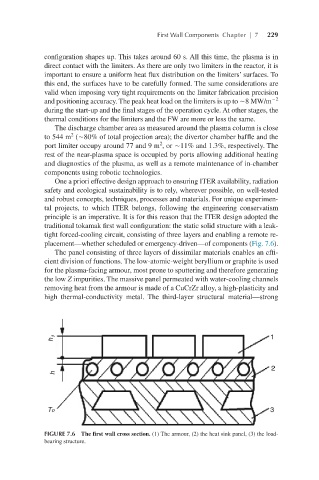
The panel consisting of three layers of dissimilar materials enables an effi-
cient division of functions. The low-atomic-weight beryllium or graphite is used
for the plasma-facing armour, most prone to sputtering and therefore generating
the low Z impurities. The massive panel permeated with water-cooling channels
removing heat from the armour is made of a CuCrZr alloy, a high-plasticity and
high thermal-conductivity metal. The third-layer structural material—strong
FIGURE 7.6 The first wall cross section. (1) The armour, (2) the heat sink panel, (3) the load-
bearing structure.