
Page 252 - Fundamentals of Magnetic Thermonuclear Reactor Design
P. 252
First Wall Components Chapter | 7 233
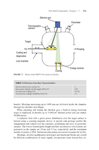
FIGURE 7.7 Sketch of the TSEFEY-M e-beam test facility.
TABLE 7.4 Electron Gun Key Characteristics
Electron beam max current (A) 5
Max power density on the target (kW/cm ) 100
2
Acceleration voltage (kV) 10–40
Acceleration voltage instability limit (%) ≤1
bracket. Mockups measuring up to 1400 mm are delivered inside the chamber
through the chamber door flange.
When adjusting and testing the electron gun, a built-in energy-receiving
2
target is employed. It absorbs up to 5 kW/cm thermal power and can endure
50,000 pulses.
A radiation field with a given power distribution over the target surface is
formed using a scanning magnetic device. A special code package enables the
management and control over the exposure, positioning and sizes of geometric
samples. The lowest thermal pulse length and time increment in which points are
generated on the sample are 10 ms and 3.3 µs, respectively, and the maximum
number of points is 2048. Turbomolecular pumps are used to evacuate the facility.
Mockups, divertor qualification prototypes and functional blocks are cooled
by different combinations of water supply, low-pressure water forced-flow cir-