
Page 289 - Fundamentals of Magnetic Thermonuclear Reactor Design
P. 289
268 Fundamentals of Magnetic Thermonuclear Reactor Design
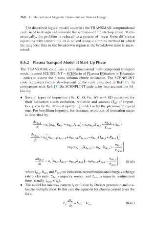
The described logical model underlies the TRANSMAK computational
code, used to design and simulate the scenarios of the start-up phase. Math-
ematically, the problem is reduced to a system of linear finite-difference
equations with constraints. It is solved using a simplex method in which
the magnetic flux in the breakdown region at the breakdown time is maxi-
mised.
8.6.2 Plasma Transport Model at Start-Up Phase
The TRANSMAK code uses a zero-dimensional multicomponent transport
model (named SCENPLINT – SCENario of PLasma INitiation in Tokamaks
– code) to assess the plasma column ohmic resistance. The SCENPLINT
code represents further development of the code described in Ref. [7]. In
comparison with Ref. [7] the SCENPLINT code takes into account the fol-
lowing:
l Several types of impurities (Be, C, O, Fe, W) with 0D equations for
their ionisation states evolution, radiation and sources (S ) of impuri-
Z
ties given by the physical sputtering model or by the phenomenological
one. For beryllium impurity, for instance, evolution of ionisation states
is described by
dn Be,0 = e( − I Be,0) + − n Be,0 + S Be
0
dnBe,0dt=nenBe,1RBe,1−nBe,0IBe,0+n dt nn Be,1 R Be,1 n Be,0 n n Be,1 X Be,1 τ zloss
nBe,1XBe,1−nBe,0τzloss+SBe
0 dn Be j = + − n Bej, ( +
,
e
dt nn Bej,1 − I Be j,1 − n Bej,1 + R Be j,1 + I Be j, R Bej, )
n Be j,
+ nn ( Be j0 , 1 + X Bej, 1 − n Be j, X Bej, −
)
+
dnBe,jdt=nenBe,j−1IBe,j−1+ τ zloss
nBe,j+1RBe,j+1−nBe,jIBe,j+ dn n Be j,
e(
Be,4
RBe,j+n (nBe,j+1XBe,j+1−n-
dnBe,4dt=nenBe,3IBe,3−nBe,4RB dt = nn Be,3 I Be,3 − n Be,4 R Be,4) − n n Be0 ,4 X Be,4 − τ , (8.46)
0
Be,jXBe,j)−nBe,jτzloss
e,4−n nBe,4XBe,4−nBe,jτzloss, zloss
0
where I Be,j , R Be,j and X Be,j are ionisation, recombination and charge-exchange
rate coefficients; S is impurity source; and τ zloss is impurity confinement
Be
time (usually τ zloss = τ ).
E
l The model for runaway current I evolution by Dreicer generation and ava-
R
lanche multiplication. In this case the equation for plasma current takes the
form
LpdIPdt=Uext−Ures L p dI P = U ext − U res (8.47)
dt