
Page 29 - Fundamentals of Magnetic Thermonuclear Reactor Design
P. 29
12 Fundamentals of Magnetic Thermonuclear Reactor Design
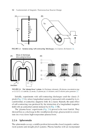
FIGURE 2.5 Systems using ‘self-contracting’ discharges. (A) Z-pinch, (B) θ-pinch [3].
FIGURE 2.6 The ‘plasma focus’ system. (A) Discharge schematic; (B) plasma concentration stag-
es (A, B, C): (1) cathode, (2) anode, (3) plasma jet, (4) insulator, and (5) electric pulse generator [3].
Initially, experiments with self-contracting discharges used the classic Z-
pinch (Fig. 2.5A), where longitudinal current I interacted with created by it cir-
Z
cumferential, or azimuthal, magnetic field. In a classic θ-pinch, the same effect
of self-contracting was produced by the interaction of a longitudinal magnetic
field with an azimuthal current induced by it (Fig. 2.5B).
The ‘plasma focus’ experiments (Fig. 2.6) proved to be most fruitful. They
showed that as a discharge in this installation develops, plasma tends to concen-
trate in a very dense high-temperature plasma focus.
2.2.6 Spheromaks
The spheromaks occupy a middle position between the closed magnetic confine-
ment systems and straight pinch systems. Plasma bunches with an incorporated