
Page 332 - Fundamentals of Magnetic Thermonuclear Reactor Design
P. 332
310 Fundamentals of Magnetic Thermonuclear Reactor Design
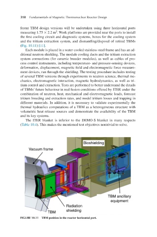
ferent TBM design versions will be undertaken using three horizontal ports
2
measuring 1.75 × 2.2 m . Work platforms are provided near the ports to install
the first cooling circuit and diagnostic systems, boxes for the cooling system
and the tritium extraction system, and dismantling/disposal of retired TBMs
(Fig. 10.11) [11].
Each module is placed in a water-cooled stainless-steel frame and has an ad-
ditional neutron shielding. The module cooling ducts and the tritium extraction
system connections (for ceramic breeder modules), as well as cables of pro-
cess control instruments, including temperature- and pressure-sensing devices,
deformation, displacement, magnetic field and electromagnetic force measure-
ment devices, run through the shielding. The testing procedure includes testing
of several TBM versions through experiments in neutron science, thermal me-
chanics, electromagnetic interaction, magnetic hydrodynamics, as well as tri-
tium control and extraction. Tests are performed to better understand the details
of TBMs’ future behaviour in real fusion conditions offered by ITER under the
combination of neutron, heat, mechanical and electromagnetic loads, forecast
tritium breeding and extraction rates, and model tritium losses and trapping in
different materials. In addition, it is necessary to validate experimentally the
thermal hydraulics computations of a TBM as a heterogeneous structure with
volumetric heat release sources and demonstrate the availability of the TBM
and its key systems.
The ITER blanket is inferior to the DEMO-S blanket in many respects
(Table 10.4). This makes the mentioned test objectives nontrivial to solve.
FIGURE 10.11 TBM position in the reactor horizontal port.