
Page 36 - Fundamentals of Magnetic Thermonuclear Reactor Design
P. 36
Facilities With Magnetic Plasma Confinement Chapter | 2 19
2.4 PHYSICAL AND ENGINEERING LIMITATIONS FOR
PARAMETER SELECTION
From the requirements mentioned earlier one can derive some of the tokamak
reactor parameters. For example, if a purely fusion reactor has a thermal power
2
of ∼3 GW and the neutron first wall load p of around 3 MW/m (Tables 2.3
n
and 2.4), as is typical for the DEMO and ARIES reactors, then plasma lateral
2
surface S must be ∼1000 m . Next, we assume that k = 1.7 and A = 4 and arrive
||
at а = ∼2 m and R = ∼8 m. With a stability margin q = 3 at the edge of a plasma
column and magnetic field B = 6 T the plasma current is ∼10 MA. These val-
t0
ues do not differ much from those given in Tables 2.1–2.4.
In this simplified (‘energy-based’) approach, plasma parameter physical
limitations are outside the analysis area. However, these parameters mainly
determine the magnetic field magnitudes, as well as the reactor configu-
ration and size. In this case, there can be ‘scissors’ between the reactor’s
physical and engineering characteristics, making the required thermonuclear
burning parameters unachievable. To sum it up, any selection of FPP, ITER
or DEMO parameters is bound to reflect a complex physics and engineering
interplay.
The problems of parameter harmonisation during designing an MFR are
addressed as part of a system analysis that studies the links between the reac-
tor’s physical and engineering limitations to identify their optimum combina-
tion and achieve the goal and purpose of a project. In the case of FPP, it is
usually the cost of electric power (net). The system analysis techniques have
proven very effective in designing the ITER, DEMO and ARIES reactors. They
allowed the parameter selection to be substantiated by physical and technical
assumptions.
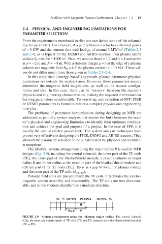
The identical system arrangement along the major radius R is used in MFR
designs (Fig. 2.9), including the central solenoid, the inner part of the TF coils
(TF ), the inner part of the blanket/shield module, a plasma column of major
i
radius R and minor radius a, the exterior part of the blanket/shield module and
exterior part of the TF coils (TF ). There is a gap between the plasma column
e
and the inner part of the TF coils (∆ PL–TF ).
Poloidal field coils are placed outside the TF coils. It facilitates the electro-
magnetic system assembly and disassembly. The TF coils are non-dismount-
able, and so the vacuum chamber has a modular structure.
FIGURE 2.9 System arrangement along the tokamak major radius. The central solenoid
(CS); the inner and exterior parts of TF coils (TF i and TF e respectively); the blanket/shield module
(BL + SH).