
Page 37 - Fundamentals of Magnetic Thermonuclear Reactor Design
P. 37
20 Fundamentals of Magnetic Thermonuclear Reactor Design
We shall only consider several key restrictions from the existing database of
the tokamak plasma physical limitations. They are as follows:
l stability margin at the edge of a plasma column (q ),
95
l plasma normalised beta (β ),
N
l plasma energy confinement time scaling coefficient (H ), and
y,2
l ratio of electron concentration in the plasma to the Greenwald plasma den-
n
Cne=nenG. sity limit C ne = n G e
A plasma toroidal beta value β can be expressed using the normalised beta β :
t
N
β = β N ⋅ I p . (2.1)
t
βt=βN100⋅IpaBt0. 100 aB t0
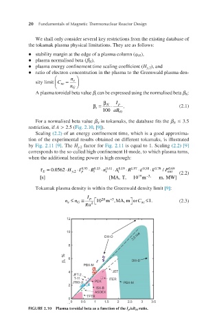
For a normalised beta value β in tokamaks, the database fits the β ≤ 3.5
N
N
restriction, if A > 2.5 (Fig. 2.10, [9]).
Scaling (2.2) of an energy confinement time, which is a good approxima-
tion of the experimental results obtained on different tokamaks, is illustrated
by Fig. 2.11 [9]. The H factor for Fig. 2.11 is equal to 1. Scaling (2.2) [9]
y.2
corresponds to the so-called high-confinement H-mode, to which plasma turns,
when the additional heating power is high enough:
0.69
τ = 0.0562 ⋅ H y,2 ⋅I 0.93 ⋅ B t 0.15 ⋅n e 0.41 ⋅ A i 0.19 ⋅ R 1.97 ε ⋅ 0.58 ⋅k 0.78 / P aux (2.2)
E
p
19
τE [s]=0.0562⋅Hy,2⋅Ip0.9 [s] [ MA,T, 10 m −3, m,MW]
3⋅Bt0.15⋅ne0.41⋅Ai0.19⋅R-
1.97⋅ε0.58⋅k0.78/Paux0.69 [MA, Tokamak plasma density is within the Greenwald density limit [9]:
T, 1019m−3, m, MW] I p
−3
n e ≤ n G ≡ 10 20 m , MA, mor C ≤1. (2.3)
ne
2
ne≤nG≡Ipπa 1020 m−3, MA, m πa 2
or Cne≤1.
FIGURE 2.10 Plasma toroidal beta as a function of the I p /aB t0 ratio.