
Page 52 - Fundamentals of Magnetic Thermonuclear Reactor Design
P. 52
34 Fundamentals of Magnetic Thermonuclear Reactor Design
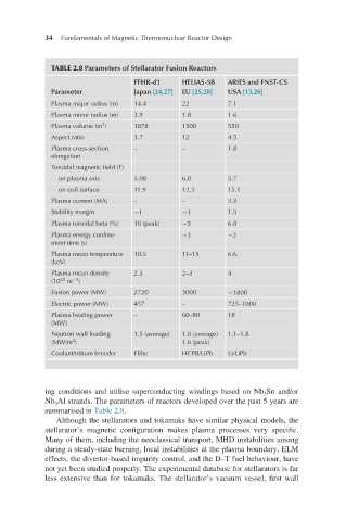
TABLE 2.8 Parameters of Stellarator Fusion Reactors
FFHR-d1 HELIAS-5B ARIES and FNST-CS
Parameter Japan [24,27] EU [25,28] USA [13,26]
Plasma major radius (m) 14.4 22 7.1
Plasma minor radius (m) 3.9 1.8 1.6
3
Plasma volume (m ) 1878 1500 550
Aspect ratio 3.7 12 4.5
Plasma cross-section – – 1.8
elongation
Toroidal magnetic field (T)
on plasma axis 5.08 6.0 5.7
on coil surface 11.9 12.3 15.1
Plasma current (MA) – – 3.3
Stability margin ∼1 ∼1 1.5
Plasma toroidal beta (%) 10 (peak) ∼5 6.8
Plasma energy confine- ∼3 ∼2
ment time (s)
Plasma mean temperature 10.5 11–15 6.6
(keV)
Plasma mean density 2.5 2–3 4
−3
20
(10 m )
Fusion power (MW) 2720 3000 ∼1800
Electric power (MW) 457 – 725–1000
Plasma heating power – 60–80 18
(MW)
Neutron wall loading 1.5 (average) 1.0 (average) 1.1–1.8
2
(MW/m ) 1.6 (peak)
Coolant/tritium breeder Flibe HCPB/LiPb Li/LiPb
ing conditions and utilise superconducting windings based on Nb Sn and/or
3
Nb Al strands. The parameters of reactors developed over the past 5 years are
3
summarised in Table 2.8.
Although the stellarators and tokamaks have similar physical models, the
stellarator’s magnetic configuration makes plasma processes very specific.
Many of them, including the neoclassical transport, MHD instabilities arising
during a steady-state burning, local instabilities at the plasma boundary, ELM
effects, the divertor-based impurity control, and the D–T fuel behaviour, have
not yet been studied properly. The experimental database for stellarators is far
less extensive than for tokamaks. The stellarator’s vacuum vessel, first wall