
Page 179 - Fundamentals of Ocean Renewable Energy Generating Electricity From The Sea
P. 179
168 Fundamentals of Ocean Renewable Energy
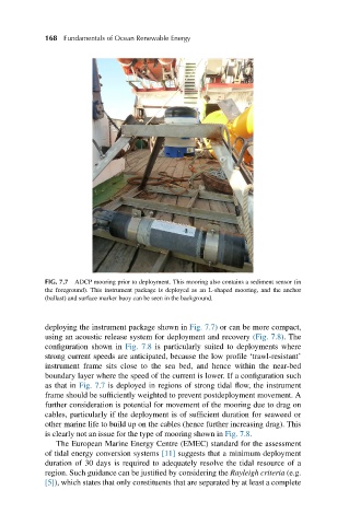
FIG. 7.7 ADCP mooring prior to deployment. This mooring also contains a sediment sensor (in
the foreground). This instrument package is deployed as an L-shaped mooring, and the anchor
(ballast) and surface marker buoy can be seen in the background.
deploying the instrument package shown in Fig. 7.7) or can be more compact,
using an acoustic release system for deployment and recovery (Fig. 7.8). The
configuration shown in Fig. 7.8 is particularly suited to deployments where
strong current speeds are anticipated, because the low profile ‘trawl-resistant’
instrument frame sits close to the sea bed, and hence within the near-bed
boundary layer where the speed of the current is lower. If a configuration such
as that in Fig. 7.7 is deployed in regions of strong tidal flow, the instrument
frame should be sufficiently weighted to prevent postdeployment movement. A
further consideration is potential for movement of the mooring due to drag on
cables, particularly if the deployment is of sufficient duration for seaweed or
other marine life to build up on the cables (hence further increasing drag). This
is clearly not an issue for the type of mooring shown in Fig. 7.8.
The European Marine Energy Centre (EMEC) standard for the assessment
of tidal energy conversion systems [11] suggests that a minimum deployment
duration of 30 days is required to adequately resolve the tidal resource of a
region. Such guidance can be justified by considering the Rayleigh criteria (e.g.
[5]), which states that only constituents that are separated by at least a complete