
Page 249 - Fundamentals of Radar Signal Processing
P. 249
Let t = 0 for simplicity; the results can be adjusted for any other delay t by
0
0
shift invariance. Renaming the simple pulse matched filter output from Eq.
(4.19) as s (t), Eq. (4.56) becomes
p
(4.57)
where the symmetry of s (t) has been used in the last step. Equation (4.57) states
p
that the matched filter output is a superposition of shifted copies of s (t). The
p
double summation can be simplified by noting that all terms that have the same
value of (n – m) are identical and can be combined. There are M combinations
of m and n such that m – n = 0, namely, all those where m = n. There are M – 1
cases where m – n = +1 and another M – 1 cases where m – n = –1. Continuing
in this vein gives
(4.58)
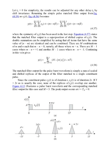
The matched filter output for the pulse burst waveform is simply a sum of scaled
and shifted replicas of the output of the filter matched to a single constituent
pulse.
Since the constituent pulse x (t) is of duration τ, s (t) is of duration 2τ. If T
p
p
> 2τ as is usually the case, none of the replicas of s (t) overlap one another.
p
Figure 4.13 illustrates a pulse burst waveform and the corresponding matched
filter output for this case and M = 3. The peak output occurs at t = T = 0:
M