
Page 254 - Fundamentals of Radar Signal Processing
P. 254
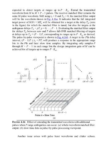
expected  to  detect  targets  at  ranges  up  to P  ·  R .  Extend  the  transmitted
                                                                              ua
               waveform from M to M + P – 1 pulses. The receiver matched filter remains the
               same M-pulse waveform. Still using t  = 0 and T  = 0, the matched filter output
                                                                         M
                                                            0
               will be the waveform shown in Fig. 4.16a. It indicates that the full integrated
                                       2
               target power of MA τ = ME  will be obtained for a target at the delay T  (zero
                                                                                                     M
                                                p
               in the figure) for which the matched filter is tuned, but also for targets at the
               ambiguous delays T  + pT, p = 0, …, P – 1. Evaluating the matched filter output
                                      M
               for delays T  between zero and T allows full-SNR matched filtering of targets
                              M
               at delays up to T  + (P – 1)T, corresponding to ranges up to P · R  as desired.
                                   M
                                                                                              ua
               The pulse-by-pulse viewpoint is shown in Fig. 4.16b. A target in the Pth delay
               interval, (P – 1)T ≤ t  < PT, will produce a response in the appropriate range
                                         0
               bin  in  the Pth  and  later  slow  time  samples.  By  integrating  only  samples P
               through M + P – 1 in each range bin the design integration gain of M can be

               achieved for all targets up to ranges P · R .
                                                                ua


               FIGURE 4.16   Effect of extending the transmitted waveform with additional
               pulses when P range ambiguities can occur: (a) whole-waveform matched filter
               output. (b) slow-time data in pulse-by-pulse processing viewpoint.


                     Another  issue  arises  with  pulse  burst  waveforms  and  clutter  echoes.