
Page 269 - Fundamentals of Radar Signal Processing
P. 269
proper matched filtering achieves a signal processing gain of G = βτ compared
sp
to a simple pulse of the same Rayleigh resolution.
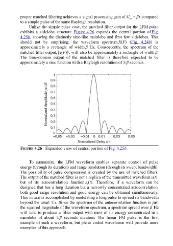
Unlike the simple pulse case, the matched filter output for the LFM pulse
exhibits a sidelobe structure. Figure 4.26 expands the central portion of Fig.
4.25b, showing the distinctly sinc-like mainlobe and first few sidelobes. This
should not be surprising: the waveform spectrum X(F) (Fig. 4.24b) is
approximately a rectangle of width β Hz. Consequently, the spectrum of the
2
matched filter output, |X(F)| , will also be approximately a rectangle of width β.
The time-domain output of the matched filter is therefore expected to be
approximately a sinc function with a Rayleigh resolution of 1/β seconds.
FIGURE 4.26 Expanded view of central portion of Fig. 4.25b.
To summarize, the LFM waveform enables separate control of pulse
energy (through its duration) and range resolution (through its swept bandwidth).
The possibility of pulse compression is created by the use of matched filters.
The output of the matched filter is not a replica of the transmitted waveform x(t),
but of its autocorrelation function s (t). Therefore, if a waveform can be
x
designed that has a long duration but a narrowly concentrated autocorrelation,
both good range resolution and good energy can be obtained simultaneously.
This in turn is accomplished by modulating a long pulse to spread its bandwidth
beyond the usual 1/τ. Since the spectrum of the autocorrelation function is just
the squared magnitude of the waveform spectrum, a spectrum spread over β Hz
will tend to produce a filter output with most of its energy concentrated in a
mainlobe of about 1/β seconds duration. The linear FM pulse is the first
example of such a waveform, but phase coded waveforms will provide more
examples of this approach.