
Page 289 - Fundamentals of Radar Signal Processing
P. 289
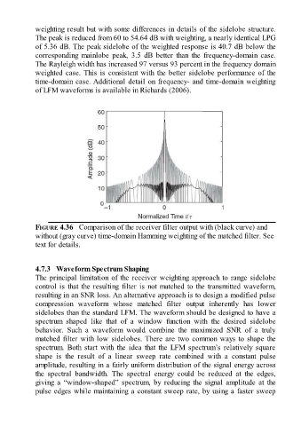
weighting result but with some differences in details of the sidelobe structure.

               The peak is reduced from 60 to 54.64 dB with weighting, a nearly identical LPG
               of 5.36 dB. The peak sidelobe of the weighted response is 40.7 dB below the
               corresponding  mainlobe  peak,  3.5  dB  better  than  the  frequency-domain  case.
               The Rayleigh width has increased 97 versus 93 percent in the frequency domain
               weighted case. This is consistent with the better sidelobe performance of the
               time-domain case. Additional detail on frequency- and time-domain weighting

               of LFM waveforms is available in Richards (2006).


               FIGURE 4.36   Comparison of the receiver filter output with (black curve) and

               without (gray curve) time-domain Hamming weighting of the matched filter. See
               text for details.


               4.7.3   Waveform Spectrum Shaping
               The principal limitation of the receiver weighting approach to range sidelobe
               control is that the resulting filter is not matched to the transmitted waveform,
               resulting in an SNR loss. An alternative approach is to design a modified pulse
               compression  waveform  whose  matched  filter  output  inherently  has  lower
               sidelobes than the standard LFM. The waveform should be designed to have a

               spectrum  shaped  like  that  of  a  window  function  with  the  desired  sidelobe
               behavior.  Such  a  waveform  would  combine  the  maximized  SNR  of  a  truly
               matched filter with low sidelobes. There are two common ways to shape the
               spectrum.  Both  start  with  the  idea  that  the  LFM  spectrum’s  relatively  square
               shape  is  the  result  of  a  linear  sweep  rate  combined  with  a  constant  pulse
               amplitude, resulting in a fairly uniform distribution of the signal energy across

               the  spectral  bandwidth.  The  spectral  energy  could  be  reduced  at  the  edges,
               giving  a  “window-shaped”  spectrum,  by  reducing  the  signal  amplitude  at  the
               pulse edges while maintaining a constant sweep rate, by using a faster sweep