
Page 338 - Fundamentals of Radar Signal Processing
P. 338
target is approaching or receding, or at what radial velocity. Furthermore, it
provides no indication of the number of moving targets present. If multiple
moving targets are present in the slow-time signal from a particular range the
result will still be only a “target present” decision from the detector. On the
other hand, MTI processing is very simple and computationally undemanding.
Despite its simplicity, a well-designed MTI can improve the SCR by several to
sometimes 20 or more decibels in some clutter conditions.
5.2.1 Pulse Cancellers
The major MTI design decision is the choice of the particular MTI filter to be
used. MTI filters are typically low order, simple designs. Indeed, some of the
most common MTI filters are based on very simple heuristic design approaches.
Suppose a fixed radar illuminates a moving target surrounded by perfectly
stationary clutter. The clutter component of the echo signal from each pulse
would be identical, while the phase of the moving target component would vary
due to the changing range. Subtracting the echoes from successive pairs of
pulses would cancel the clutter components completely. The target signal would
not cancel in general due to the phase changes.
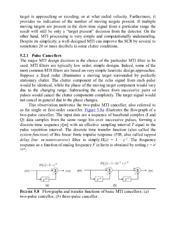
This observation motivates the two-pulse MTI canceller, also referred to
as the single or first-order canceller. Figure 5.8a illustrates the flowgraph of a
two-pulse canceller. The input data are a sequence of baseband complex (I and
Q) data samples from the same range bin over successive pulses, forming a
discrete-time sequence y[m] with an effective sampling interval T equal to the
pulse repetition interval. The discrete time transfer function (also called the
system function) of this linear finite impulse response (FIR, also called tapped
–1
delay line or nonrecursive) filter is simply H(z) = 1 – z . The frequency
response as a function of analog frequency F in hertz is obtained by setting z = e j
2πFT :
FIGURE 5.8 Flowgraphs and transfer functions of basic MTI cancellers: (a)
two-pulse canceller, (b) three-pulse canceller.