
Page 305 - Fundamentals of Reservoir Engineering
P. 305
REAL GAS FLOW: GAS WELL TESTING 241
r w r r e
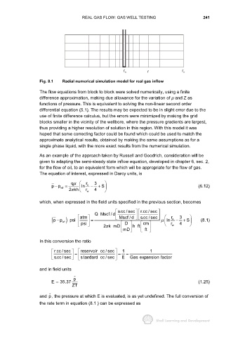
Fig. 8.1 Radial numerical simulation model for real gas inflow
The flow equations from block to block were solved numerically, using a finite
difference approximation, making due allowance for the variation of µ and Z as
functions of pressure. This is equivalent to solving the non-linear second order
differential equation (5.1). The results may be expected to be in slight error due to the
use of finite difference calculus, but the errors were minimized by making the grid
blocks smaller in the vicinity of the wellbore, where the pressure gradients are largest,
thus providing a higher resolution of solution in this region. With this model it was
hoped that some correcting factor could be found which could be used to match the
approximate analytical results, obtained by making the same assumptions as for a
single phase liquid, with the more exact results from the numerical simulation.
As an example of the approach taken by Russell and Goodrich, consideration will be
given to adapting the semi-steady state inflow equation, developed in chapter 6, sec. 2,
for the flow of oil, to an equivalent form which will be appropriate for the flow of gas.
The equation of interest, expressed in Darcy units, is
qµ r 3
pp = ln e − + S (6.12)
−
wf
2kh r w 4
π
which, when expressed in the field units specified in the previous section, becomes
s.cc / sec r.cc / sec
Q Mscf / d
atm Mscf / d s.cc / sec r 3
( pp wf ) psi = µ ln e − + S
(8.1)
−
D
psi 2k mD mD h ft cm r w 4
π
ft
In this conversion the ratio
r.cc / sec reservoir cc / sec 1 1
= = =
s.cc / sec standard cc / sec E Gas expansion factor
and in field units
p
E = 35.37 (1.25)
ZT
and p, the pressure at which E is evaluated, is as yet undefined. The full conversion of
the rate term in equation (8.1 ) can be expressed as