
Page 406 - Fundamentals of Reservoir Engineering
P. 406
IMMISCIBLE DISPLACEMENT 341
p − p = P = ∆ ρ gH (10.2)
o
c
w
where ∆ρ = ρ w - ρ o. Furthermore, considering in detail the geometry at the interface in
the capillary tube, fig. 10.4. If the curvature is approximately spherical with radius R,
then in applying the Laplace equation, (10.1), r 1 = r 2 = R at all points on the interface.
Also if r is the radius of the capillary tube, then r = RcosΘ and therefore
2σ cosΘ
p − p = P = r = ∆ ρ gh (10.3)
o
w
c
This equation is frequently used to draw a comparison between simple capillary rise
experiments, as described above, and capillary rise in the reservoir, the porous tracts
in the latter being likened to a collection of capillary tubes with different radii. In this
comparison it can be seen that the capillary rise of water will be greater for small r,
equ. (10.3), and will decrease as r increases. The decrease in capillary rise will be
apparently a continuous function due to the continuous range of pore capillaries in the
reservoir and will define, in fact, the capillary pressure-saturation relation. This
argument is frequently applied to consider the static case of water distribution above
the 100% water saturation level in the reservoir, under initial conditions, for which the
drainage capillary pressure curve is required. There will generally be no sharp interface
between the water and oil but, rather, a zone in which saturations decrease with height
above the 100% water saturation level, at which P c = 0, in accordance with the capillary
pressure (capillary rise)-saturation relationship. The vertical distance between the point
at which S w = 100%, P c = 0 and S w = S wc is called the capillary transition zone and is
denoted by H.
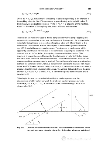
This chapter is more concerned with the effect of capillary pressure on the
displacement of oil by water, for which the imbibition capillary pressure curve is
relevant (P c = 0 at S w = 1 − S or). Consider the static situation during a water drive
shown in fig. 10.5.
∆ρgz
P c
OIL
A
y z = y cos θ
S wa
X
S = 1 - S or S wc 1 - S or
w
S
WATER w
θ z
Fig. 10.5 Determination of water saturation as a function of reservoir thickness above
the maximum water saturation plane, S w = 1− −− −S or , of an advancing waterflood