
Page 264 - Fundamentals of The Finite Element Method for Heat and Fluid Flow
P. 264
256
245
220 CONVECTION IN POROUS MEDIA
Nusselt number 195
170
145
120
100 125 150 175 200 225 250 275 300 325 350
Reynolds number
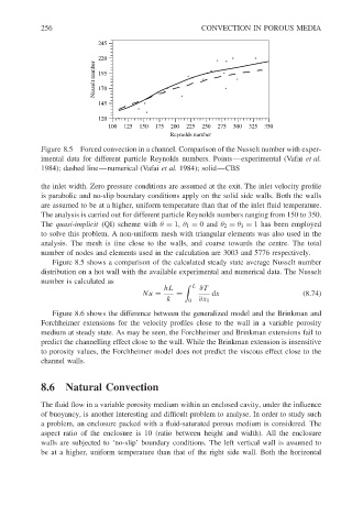
Figure 8.5 Forced convection in a channel. Comparison of the Nusselt number with exper-
imental data for different particle Reynolds numbers. Points—experimental (Vafai et al.
1984); dashed line—numerical (Vafai et al. 1984); solid—CBS
the inlet width. Zero pressure conditions are assumed at the exit. The inlet velocity profile
is parabolic and no-slip boundary conditions apply on the solid side walls. Both the walls
are assumed to be at a higher, uniform temperature than that of the inlet fluid temperature.
The analysis is carried out for different particle Reynolds numbers ranging from 150 to 350.
The quasi-implicit (QI) scheme with θ = 1, θ 1 = 0and θ 2 = θ 3 = 1 has been employed
to solve this problem. A non-uniform mesh with triangular elements was also used in the
analysis. The mesh is fine close to the walls, and coarse towards the centre. The total
number of nodes and elements used in the calculation are 3003 and 5776 respectively.
Figure 8.5 shows a comparison of the calculated steady state average Nusselt number
distribution on a hot wall with the available experimental and numerical data. The Nusselt
number is calculated as
hL L ∂T
Nu = = dx (8.74)
k 0 ∂x 1
Figure 8.6 shows the difference between the generalized model and the Brinkman and
Forchheimer extensions for the velocity profiles close to the wall in a variable porosity
medium at steady state. As may be seen, the Forchheimer and Brinkman extensions fail to
predict the channelling effect close to the wall. While the Brinkman extension is insensitive
to porosity values, the Forchheimer model does not predict the viscous effect close to the
channel walls.
8.6 Natural Convection
The fluid flow in a variable porosity medium within an enclosed cavity, under the influence
of buoyancy, is another interesting and difficult problem to analyse. In order to study such
a problem, an enclosure packed with a fluid-saturated porous medium is considered. The
aspect ratio of the enclosure is 10 (ratio between height and width). All the enclosure
walls are subjected to ‘no-slip’ boundary conditions. The left vertical wall is assumed to
be at a higher, uniform temperature than that of the right side wall. Both the horizontal