
Page 267 - Fundamentals of The Finite Element Method for Heat and Fluid Flow
P. 267
259
CONVECTION IN POROUS MEDIA
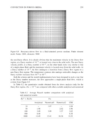
Figure 8.8 Buoyancy-driven flow in a fluid-saturated porous medium. Finite element
mesh. Nodes: 2601, elements: 5000
the non-Darcy effects. It is clearly obvious that the maximum velocity in the Darcy flow
regime, at a Darcy number of 10 −6 , is located very close to the solid walls. The non-Darcy
velocity profile, at a Darcy number of 10 −2 , on the other hand, looks very similar to that
of a single-phase fluid, and the maximum velocity is located away from the solid walls. At
a Darcy number of 10 −4 , the flow undergoes a transition from a Darcy flow regime to a
non-Darcy flow regime. The temperature contours also undergo noticeable changes as the
Darcy number increases from 10 −6 to 10 −2 .
Both the scheme and the model implementation have been designed in such a way that
as the Darcy number increases, the flow approaches a single-phase fluid flow, which is
evident from Figure 8.9
In Table 8.2, the quantitative results obtained from the above analysis (only for the
Darcy flow regime, Da < 10 −5 ) are compared with other available analytical and numerical
Table 8.2 Average Nusselt number comparison with analytical
and numerical results
∗
Ra = RaDa Nu
Analytical Numerical1 Numerical2 CBS
10 – 1.07 – 1.08
50 1.98 – 2.02 1.96
100 3.09 3.09 3.27 3.02
500 8.40 – – 8.38
1000 12.49 13.41 18.38 12.52