
Page 265 - Fundamentals of The Finite Element Method for Heat and Fluid Flow
P. 265
CONVECTION IN POROUS MEDIA
2.5 3 2 Generalized 257
Non-dimensional velocity 1.5 1 Forchhemier
Brinkman
0.5
0
0 0.5 1 1.5 2 2.5 3
Non-dimensional length
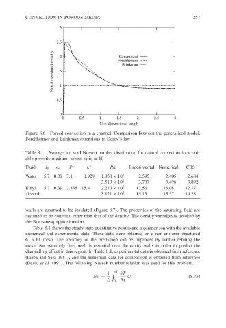
Figure 8.6 Forced convection in a channel. Comparison between the generalized model,
Forchheimer and Brinkman extensions to Darcy’s law
Table 8.1 Average hot wall Nusselt number distribution for natural convection in a vari-
able porosity medium, aspect ratio = 10
Fluid d p e Pr k ∗ Ra Experimental Numerical CBS
Water 5.7 0.39 7.1 1.929 1.830 × 10 7 2.595 2.405 2.684
3.519 × 10 7 3.707 3.496 3.892
Ethyl 5.7 0.39 2.335 15.4 2.270 × 10 8 12.56 13.08 12.17
alcohol 3.121 × 10 8 15.13 15.57 14.28
walls are assumed to be insulated (Figure 8.7). The properties of the saturating fluid are
assumed to be constant, other than that of the density. The density variation is invoked by
the Boussinesq approximation.
Table 8.1 shows the steady state quantitative results and a comparison with the available
numerical and experimental data. These data were obtained on a non-uniform structured
61 × 61 mesh. The accuracy of the prediction can be improved by further refining the
mesh. An extremely fine mesh is essential near the cavity walls in order to predict the
channelling effect in this region. In Table 8.1, experimental data is obtained from reference
(Inaba and Seki 1981), and the numerical data for comparison is obtained from reference
(David et al. 1991). The following Nusselt number relation was used for this problem.
1 L ∂T
Nu = dx (8.75)
L 0 ∂x