
Page 274 - Fundamentals of The Finite Element Method for Heat and Fluid Flow
P. 274
SOME EXAMPLES OF FLUID FLOW AND HEAT TRANSFER PROBLEMS
266
are available in Chapter 7. In this subsection, two important benchmark problems that
are commonly employed in testing codes will be discussed. In addition, a very recently
proposed benchmark test case will also be considered.
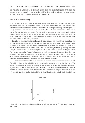
Flow in a lid-driven cavity
Flow in a lid-driven cavity is one of the most widely used benchmark problems to test steady
state incompressible fluid dynamics codes. Our interest will be to present this problem as a
benchmark for the steady state solution. The definition of the problem is given in Figure 9.1.
The geometry is a simple square enclosure with solid walls on all four sides. All the walls,
except for the top one, are fixed. The top wall is assumed to be moving with a given
velocity; therefore, the fluid attached to this wall also moves with the same velocity in the
direction shown in Figure 9.1. A pressure value of zero is forced at the node in the bottom
left-hand corner of the cavity as shown.
In order to demonstrate the influence of mesh density on the solution procedure, six
different meshes have been selected for this problem. We start with a very coarse mesh,
as shown in Figure 9.2(a), and refine uniformly by increasing the number of elements as
shown in the fourth mesh (Figure 9.2(d)). The fifth mesh is generated by refining the mesh
along the cavity walls and coarsening the mesh at the centre as shown in Figure 9.2(e).
The meshes shown in Figures 9.2(a) to (e) are all unstructured in nature. The sixth and
final mesh is a structured mesh of 100 × 100 uniform divisions, as shown in Figure 9.2(f).
At this point, the readers are reminded that a structured mesh gives better accuracy as
compared to an unstructured mesh for the same number of nodes.
A Reynolds number of 5000 is selected to demonstrate the influence of mesh refinement.
The initial values of the velocities at all inside nodes are taken as u 1 = 1and u 2 = 0. The
pressure is assumed to be equal to zero at the beginning of the computation. The semi-
implicit form of the CBS scheme (see Chapter 7) was used to calculate the solution in
time for all the six meshes. Non-dimensional time step values, ranging between 10 −3 and
10 −2 , were employed in the calculations. In order to achieve a steady state solution, the
u = 1, u = 0
1
2
u 2 = 0 u 2 = 0
u 1 = u 1 =
p = 0
u = u = 0
2
1
Figure 9.1 Incompressible isothermal flow in a lid-driven cavity. Geometry and boundary
conditions