
Page 276 - Fundamentals of The Finite Element Method for Heat and Fluid Flow
P. 276
SOME EXAMPLES OF FLUID FLOW AND HEAT TRANSFER PROBLEMS
268
calculation was continued until the maximum difference of the variables u 1 , u 2 and p
−6
. Other criteria, as discussed in
between two consecutive time steps became less than 10
Chapter 7, could also have been employed to decide whether the steady state solution had
been reached.
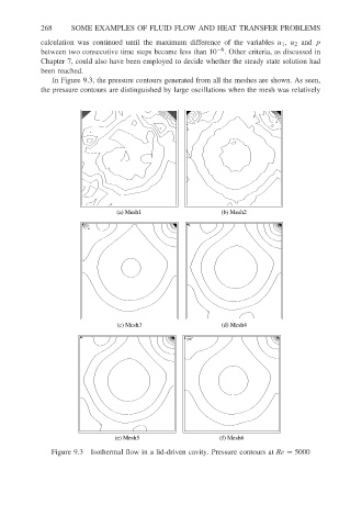
In Figure 9.3, the pressure contours generated from all the meshes are shown. As seen,
the pressure contours are distinguished by large oscillations when the mesh was relatively
(a) Mesh1 (b) Mesh2
(c) Mesh3 (d) Mesh4
(e) Mesh5 (f) Mesh6
Figure 9.3 Isothermal flow in a lid-driven cavity. Pressure contours at Re = 5000