
Page 280 - Fundamentals of The Finite Element Method for Heat and Fluid Flow
P. 280
SOME EXAMPLES OF FLUID FLOW AND HEAT TRANSFER PROBLEMS
272
2L Parabolic u 1 and u 2 = 0
u 1 = u 2 = 0 p = 0
L
4L 36L
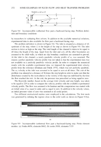
Figure 9.8 Incompressible isothermal flow past a backward-facing step. Problem defini-
tion and boundary conditions
by researchers in validating flow solvers. In addition to the available numerical solutions,
experimental data is also available for flow past a backward-facing step.
The problem definition is shown in Figure 9.8. The inlet is situated at a distance of 4L
upstream of the step, where L is the height of the step as shown in Figure 9.8. The inlet
section is twice as high as the step. The total length of the channel is taken to be equal to
40 times the height of the step. Apart from the inlet and exit, all the other boundaries are
assumed to be solid walls, in which no slip boundary conditions are assumed to prevail.
At the inlet to the channel, a nearly parabolic velocity profile of u 1 was assumed. The
reason a perfect parabolic velocity profile was not taken is that the experimental data was
not available on a perfectly parabolic velocity profile. In order to compare the numerical
results with the available experimental data, we imposed the experimental inlet velocity
profile from the reference (Denham and Patrik 1974), which was not perfectly parabolic.
The u 2 velocity at the inlet was assumed to be equal to zero at all times. The exit of the
problem was situated at a distance of 36 times the step height in order to make sure that the
disturbance created by the recirculation in the vicinity of the step was stabilized by the time
the flow reached the exit. At the exit, the pressure was prescribed as being equal to zero.
The Reynolds number, based on the average inlet velocity and step height, was taken
to be equal to 229 in order to compare the velocity profiles with the available experimental
velocity profile. The flow was assumed to be laminar and the computation was started with
an initial value of u 1 equal to unity and u 2 equal to zero. In addition to the velocity values,
an initial pressure value of zero was assumed at all nodal points.
Two different unstructured meshes were employed in the calculations. The first mesh
was generated by refining the regions close to the solid walls as shown in Figure 9.9(a).
(a)
(b)
Figure 9.9 Incompressible isothermal flow past a backward-facing step. Finite element
meshes. (a) Nodes:4656, elements:8662, (b) nodes:3818, elements:7155