
Page 285 - Fundamentals of The Finite Element Method for Heat and Fluid Flow
P. 285
SOME EXAMPLES OF FLUID FLOW AND HEAT TRANSFER PROBLEMS
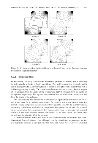
(a) Re = 50 (b) Re = 100 277
(c) Re = 400 (d) Re = 1000
Figure 9.14 Incompressible isothermal flow in a double-driven cavity. Pressure contours
for different Reynolds numbers
9.2.2 Transient flow
In this section, a widely used transient benchmark problem of periodic vortex shedding
behind a circular cylinder is briefly considered. The problem definition is simple and is
shown in Figure 9.16. A circular cylinder of diameter D is placed in a fluid stream with a
uniform approaching velocity. The computational domain inlet and exit are placed at lengths
of 4D upstream from the centre of the cylinder and 12D downstream from the centre of
the cylinder respectively. The top and bottom boundaries are situated at a distance of 4D
from the centre of the cylinder.
The inlet velocity was assumed to be uniform with a prescribed non-zero value for u 1
and a zero value for u 2 velocity components. On both the bottom and the top sides, the
normal velocity component u 2 was assumed to be equal to zero. On the cylinder surface,
the no-slip condition of zero velocity components was applied. At the exit, the pressure
value was assumed to be constant. In this study, a zero value for pressure was assumed
at the exit. The inlet Reynolds number was defined on the basis of the free stream inlet
velocity and the diameter D of the cylinder.
A three-dimensional mesh was used in the vortex-shedding calculations. For three-
dimensional flow calculations, two additional boundary conditions are necessary on the
two additional surfaces at the front and the back (see Figure 9.17). The two additional