
Page 209 - Fundamentals of Water Treatment Unit Processes : Physical, Chemical, and Biological
P. 209
164 Fundamentals of Water Treatment Unit Processes: Physical, Chemical, and Biological
Flotation basin
Solids collection trough
Rapid Thickened solids mat
mix Flocculators Skimmers
Q
Separation zone
Weir
Coagulant Paddle wheels Collection pipe
To filter
Dissolved air diffuser
Contact zone
Valve
Q(air) R
P
Saturator
Q(air, excess)
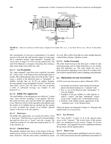
FIGURE 8.1 Side-view schematic of DAF system. (Adapted from Valade, M.T. et al., J. Am. Water Works Assoc., 88(12), 36, December,
1996.)
The concentration of each gas is proportional to its partial of a weir. The overflow from this box enters another head box
pressure in the tank (the total pressure ranges 4–8 atm gage) control before entering a filtration system.
and is sometimes termed ‘‘super-saturated.’’ Typically, the
recycle flow, R, ranges 5%–15% of Q, the influent flow. The 8.2.1.9 Further Processing
water flow bifurcates at each piece of packing, thus creating a The solids stream leaving by the float layer is subject to add-
large water surface area within the voids. itional processing, such as further thickening, e.g., by centrifu-
ging, belt filter-press, etc. The water stream also may be
8.2.1.5 Gas Precipitation processed further, depending on the context. For example, filtra-
The ‘‘super-saturated’’ water flows into a manifold, just under tion would beexpected ifthe context isdrinking-watertreatment.
the ‘‘contact zone’’ of the flotation basin and through a bank of
nozzles. The sudden pressure drop across the nozzle ‘‘throat’’ 8.3 PRINCIPLES OF DAF FLOTATION
causes a portion of the dissolved gases to ‘‘precipitate’’ as
bubbles, typically they are 20–50 mm median diameter; A DAF system has four process phases (Edzwald, 1995):
the mass quantity of gas precipitated is termed ‘‘released’’ gas
(also called ‘‘excess’’ gas). The effect is the same as opening 1. Gas transferacrossthe air–water interface (from thegas
a bottle of carbonated beverage (see Chapter 18 and phase to the dissolved phase) in a ‘‘saturator’’ tank.
Section H.3.1). 2. Gas, i.e., air, in the dissolved state ‘‘precipitates’’ to
form gas bubbles.
8.2.1.6 Bubble–Floc Agglomerate 3. Transport of the gas bubbles to solid particles to
The small bubbles of precipitated gas rise within the ‘‘contact achieve ‘‘contact’’ and then ‘‘attachment’’ (which
zone’’ with a fraction ‘‘attaching’’ to floc particles. The bub- occurs in the ‘‘contact zone’’ of the flotation basin).
bles create buoyancy and cause the bubble–floc agglomerate 4. Flotation of the bubble–particle agglomerate in the
to rise. Their rise velocity in the separation zone depends upon ‘‘separation zone’’ of the flotation basin.
the number of air bubbles that are attached per floc particle
(or more accurately the volume of air bubbles attached These four phases are illustrated in Figure 8.1. Principles that
relative to the mass of the floc particle). underlie them are reviewed here.
8.2.1.7 Float Layer
8.3.1 GAS TRANSFER
The bubble–floc agglomerate, as it reaches the surface, forms
a ‘‘float layer.’’ The float layer is removed by skimmer blades The ‘‘mass transfer’’ of gases in air to the aqueous phase
that push the float over a ‘‘beach’’ and into a trough. The occurs in the ‘‘saturator.’’ The several facets of this process
solids flow is about 2%–4% solids and consumes about 1%–2% phase are summarized in this section. Chapter 18 reviews
of the total flow, Q. ‘‘gas transfer,’’ and Appendix H reviews equilibrium between
the gas phase and the aqueous phase.
8.2.1.8 Clarified Water
The partially clarified water leaves at the bottom of the sep- 8.3.1.1 Henry’s Law
aration zone by means of a set of perforated collection pipes to The gas phase–aqueous phase equilibrium is given by Henry’s
enter a head box, with the water surface controlled by means law, which states merely that the equilibrium concentration of