
Page 212 - Fundamentals of Water Treatment Unit Processes : Physical, Chemical, and Biological
P. 212
Flotation 167
where pressurized by a pump to the required saturator pressure,
H(air) is the Henry’s constant for air (kg dissolved air=m 3 usually in the range of 400 P(saturator) 800 kPa gage
water=kPa air); a value for H(air) may beapproximated asa (4–8 atm gage), and leaves at a concentration, C(saturator) e ,
calculated as per Equation 8.5. The airflow, Q a (STP), enters
weighted average for H(O 2 )and H(N 2 ), i.e., H(O 2 þ N 2 )
3
0.000238 (kg O 2 þ N 2 in gas phase=m water=kPa air) the system and is compressed to the saturator pressure; the
P(saturator) is the pressure of gas air in saturator tank, airflow is ‘‘dead-ended,’’ i.e., no airflow leaves the system,
i.e., at gas–water interface (kPa) and thus the air is supplied at the rate of dissolution. The
change in mass flow of dissolved air through the saturator,
The saturator pressure should be sufficient to provide i.e., R[C(saturator) C a ], equals the rate of gas dissolution
the required value of C(saturator), i.e., in order to provide the from the airflow, i.e., Q(STP) r(STP). Although the airflow
bubbles needed to float the particles entering the contact zone. is shown as entering the saturator through a compressor, a
traditional means to supply air is by an intake on the suction
8.3.1.4 Gas Concentration at Nozzle Depth side of the pump (see, e.g., Kalinske, 1958, p. 225), which
The concentrations of dissolved gases collectively, i.e., air, at requires the pump to be set at an elevation that results in a
the depth of nozzle submergence, C a , is also calculated by negative gage pressure at the pump inlet.
Henry’s law, i.e.,
8.3.1.6 Saturator Packing
Figure 8.3 shows (a) an ‘‘unpacked’’ saturator, and (b) a
C a ¼ H(air)
‘‘packed’’ saturator. In each case, the purpose is to generate
D(nozzle) a high air–water interfacial area so that the oxygen and nitro-
101:325 (8:7)
10:33 m
P(atm-at-Z-elev) þ gen (comprising 0.99 fraction of air) and the minor gases may
transfer from the gas state to the dissolved state.
For both the unpacked and packed saturators, the water
where
H(air) is the Henry’s constant for air (kg dissolved air=m 3 flows through a distribution plate at the top; the water at the
bottom of the saturator is ‘‘ponded.’’ With the unpacked
water=kPa air); a value for H(air) may be approximated
saturator, i.e., Figure 8.3a, the gas transfer occurs as the
as a weighted average for H(O 2 ) and H(N 2 ), i.e.,
3 water falls, and by the entrained air in the flow that plunges
H(O 2 þ N 2 ) 0.000238 (kg O 2 þ N 2 in gas phase=m
into the ‘‘pool’’ at the bottom. With the packed-bed saturator,
water=kPa air)
i.e., Figure 8.3b, the gas transfer occurs mostly within the
P(atm) is the pressure of air at elevation of flotation tank
packing interstices due to the large air–water surface area
(kPa)
created by the bifurcation in flow at each packing object
D(nozzle) is the depth of nozzle and manifold (m)
comprising the bed. A valve located after the saturator can
10.33 m is the depth of water having pressure of 1.0 atm or
control the flow, R, and the level of the ‘‘ponding.’’ A water
101.325 kPa
manometer, shown in each diagram, can monitor the level of
the ‘‘ponded’’ water (the air pressure operates on both sides of
The value of C a is also the concentration at which gas
the manometer and so the differential is the water depth, as
precipitation occurs and is the maximum concentration of
shown). Empirical guidelines for saturator design and
gas in solution.
operation are (Edzwald, 1995, p. 16)
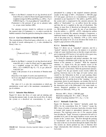
8.3.1.5 Saturator Mass Balance
Pressure: 400 P(sat) 800 kPa gage
Figure 8.2 shows the flows of water and air entering and
Hydraulic loading rate: 50 HLR 80 m=h
leaving the saturator tank. As seen, the recycle flow, R, enters
Depth of packing material: 0.8 Z D 1.2 m
the system at a dissolved air concentration, C a , and is
8.3.1.7 Hydraulic Grade Line
Figure 8.4 illustrates the ‘‘relative’’ hydraulic grade line
Pressure, i.e., P(tank) (HGL) for the recirculation flow, R; ‘‘relative’’ means the
R HGL (locus of points of pressure head plus elevation head)
P
C a is located with respect to atmospheric pressure (i.e., gage
Saturator pressure). The important points are (1) the saturator pump
must develop the ‘‘head’’ necessary to pressurize the tank to a
Valve Q(air, STP)
P specified level, and (2) the major headloss occurs across the
ρ(air, STP) nozzles in the ‘‘contact zone.’’ The flow through the packing
R Valve is ‘‘unsaturated’’ and so the headloss across the packing is
due only to the loss in elevation through the depth of the bed.
C(saturator)
The nozzles are shown pointed up only to illustrate their
FIGURE 8.2 Schematic showing materials balance of gases for shape schematically; their direction, as installed, would be
saturator. horizontal.