
Page 213 - Fundamentals of Water Treatment Unit Processes : Physical, Chemical, and Biological
P. 213
168 Fundamentals of Water Treatment Unit Processes: Physical, Chemical, and Biological
P
P
R, C , P(sat)
a
R, C , P(sat)
a
Distribution plate
Distribution plate
Q(air)e=0 Q(air)e=0
Packing Z D
Manometer for
tank water level
Q(air)
Q(air)
R, C(saturator) R, C(saturator)
(a) (b)
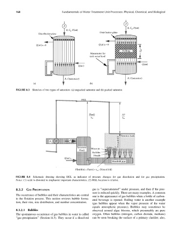
FIGURE 8.3 Sketches of two types of saturators: (a) unpacked saturator and (b) packed saturator.
HGL
P(sat) ΔP
–—–— –—
γ w γ w
Flotation tank
P R
P 1 D(manifold)
Saturator Water jet
P(sat)
Bubbles
Nozzle
Q(air) in
Manifold pipe
P(bubble) =P(atm)+γ w· D(manifold)
FIGURE 8.4 Schematic drawing showing HGL as indicator of pressure changes for gas dissolution and for gas precipitation.
Notes: (1) scale is distorted to emphasize important characteristics, (2) HGL location is relative.
8.3.2 GAS PRECIPITATION gas is ‘‘supersaturated’’ under pressure, and then if the pres-
sure is reduced quickly. There are many examples. A common
The occurrence of bubbles and their characteristics are central
one is the appearance of gas bubbles when a bottle of carbon-
to the flotation process. This section reviews bubble forma-
ated beverage is opened. Boiling water is another example
tion, their size, size distribution, and number concentration.
(gas bubbles appear when the vapor pressure of the water
equals atmospheric pressure). Bubbles may sometimes be
8.3.2.1 Bubbles observed around algae blooms, which presumably are pure
The spontaneous occurrence of gas bubbles in water is called oxygen. Often bubbles (nitrogen, carbon dioxide, methane)
‘‘gas precipitation’’ (Section H.3). They occur if a dissolved can be seen breaking the surface of a primary clarifier; also,